Weight assembly for golf club head
- Summary
- Abstract
- Description
- Claims
- Application Information
AI Technical Summary
Benefits of technology
Problems solved by technology
Method used
Image

Examples
first embodiment
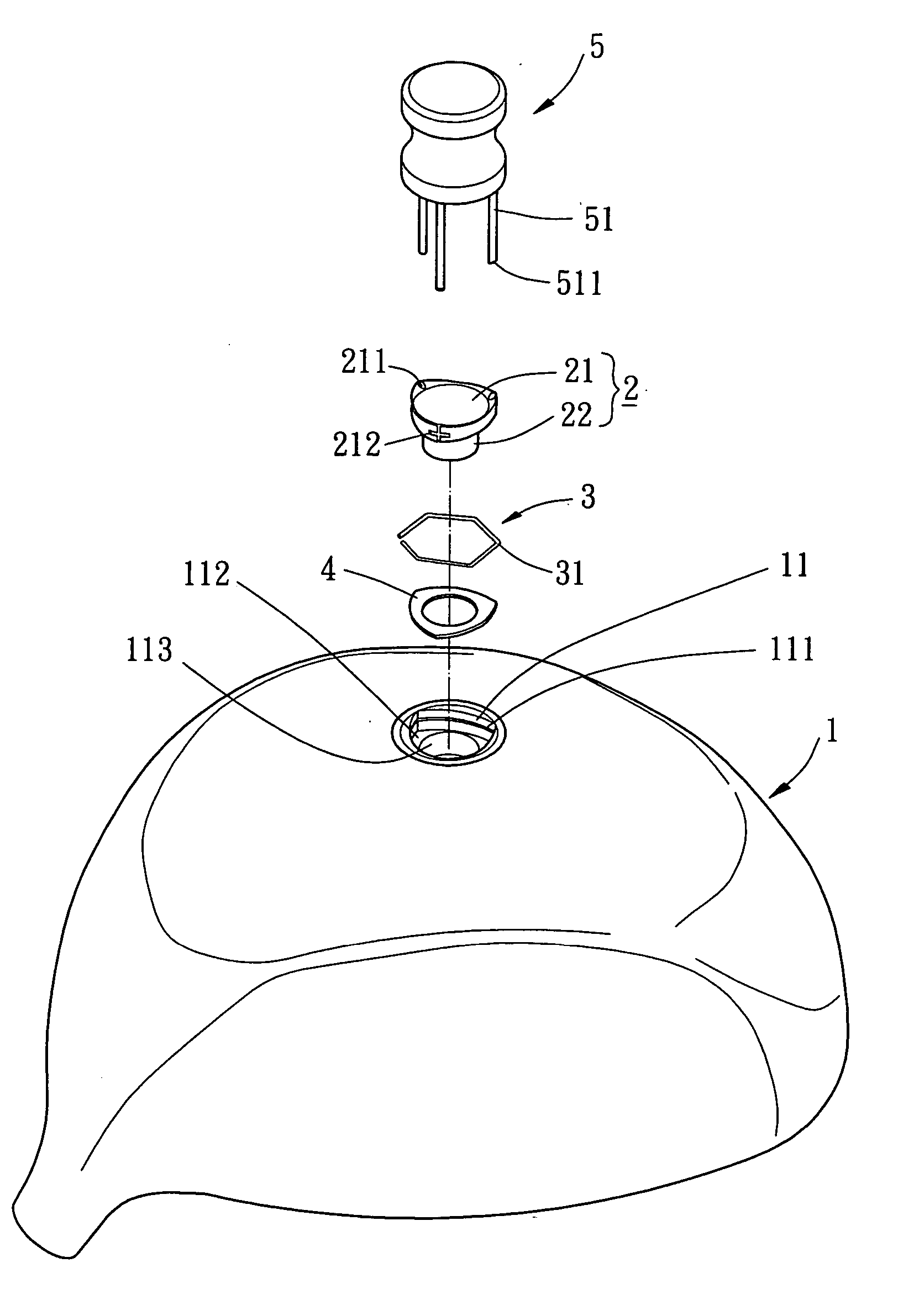
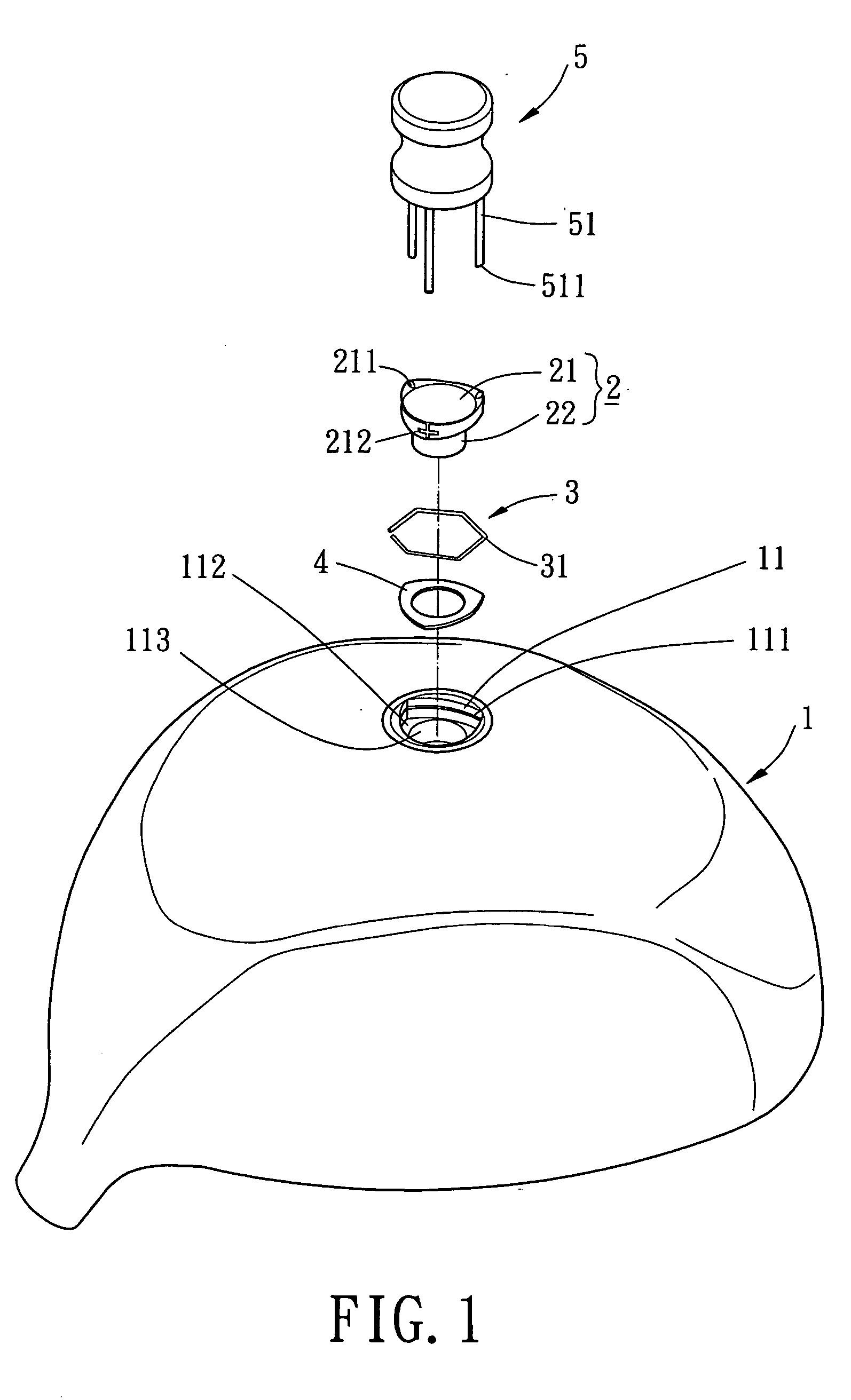
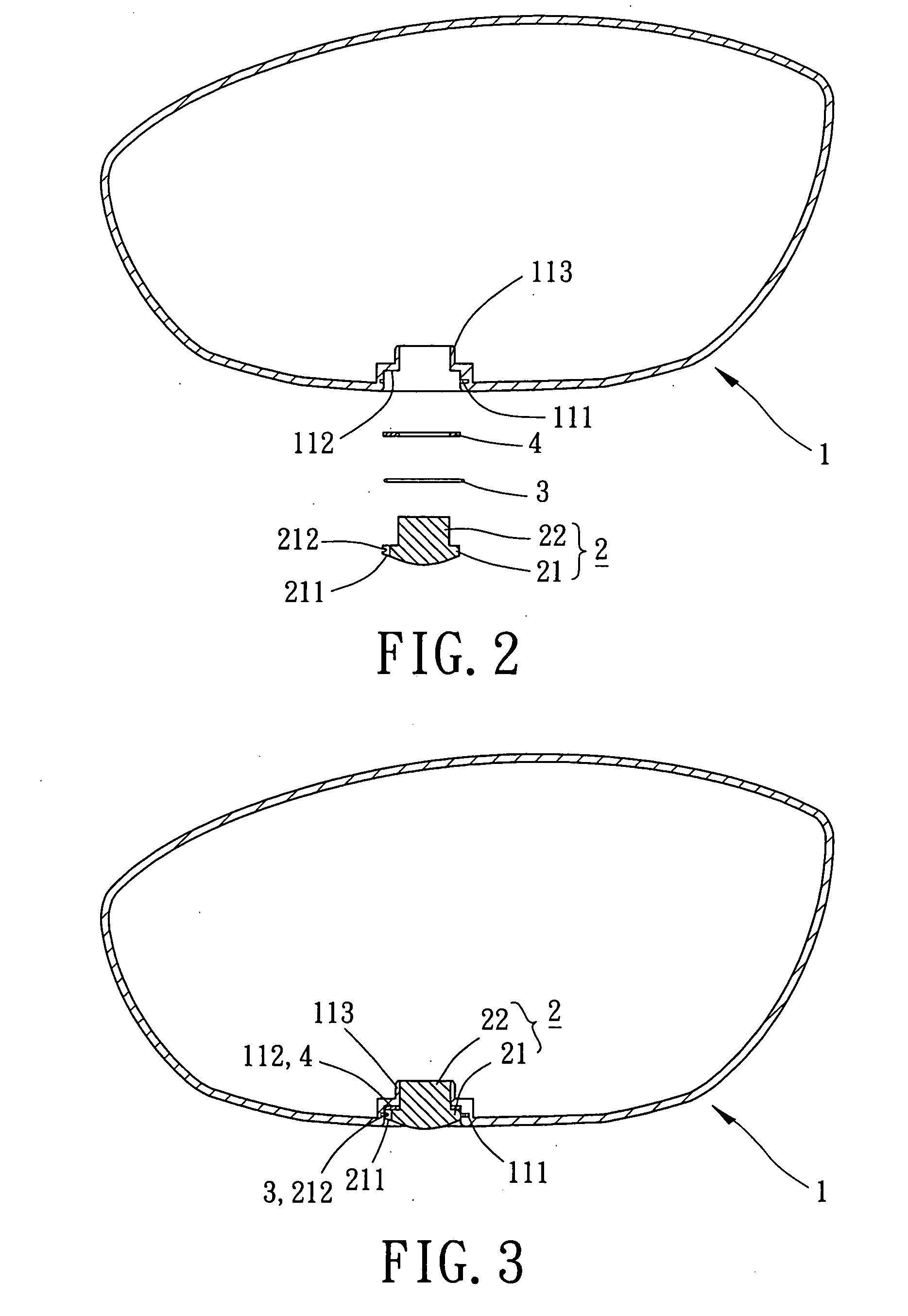
[0035]FIG. 1 shows a golf club head with a weight assembly in accordance with the present invention. FIG. 2 is an exploded sectional view of the golf club head in FIG. 1. FIG. 3 is a sectional view of the golf club head.
[0036] The golf club head comprises a body 1, a weight 2, a positioning resilient member 3, and a vibration-absorbing member 4. The weight 2 can be mounted to and fastened in the body 1 in assembling operation, or unfastened and detached from the body 1 by an unlatching member 5 in disassembling operation. The body 1 is made of stainless steel, carbon steel, alloy steel, Fe—Mn—Al alloy, or carbon fiber by casting, forging, or mechanical processing. In the illustrated embodiment, the body 1 is of a wood type club head. Detail description of the body 1 is omitted to avoid redundancy.
[0037] The body 1 includes an engaging seat 11 in a sole thereof. The engaging seat 11 is preferably a recessed portion adjacent to a rear of the body 1. Preferably, the engaging seat 11 i...
second embodiment
[0047]FIG. 5 shows the present invention, wherein the extension 113 has a closed bottom end. Further, another vibration-absorbing member 41 is mounted to the closed bottom end of the extension 113 and in contact with the shank 22 of the weight 2. Accordingly, an installation space for the vibration-absorbing member 4 and an interactive area between the engaging seat 11 and the vibration-absorbing member 41 can be increased that may enhance vibration-absorbing effect. Furthermore, the full engagement of the shank 22 of the weight 2 with the vibration-absorbing member 41 results in an increase of the engagement of the weight 2 with the engaging seat 11.
third embodiment
[0048]FIG. 6 shows the present invention, wherein a plurality of engaging seats 11 are defined in the sole or other portions of the body 1. Each engaging seat 11 receives a weight assembly including a weight 2, a positioning resilient member 3, and a vibration-absorbing member 4 described above. The engaging seats 11 can be formed on the skirt of the body 1 and selectively located adjacent to the rear, toe, or heel of the body 1. The weights 2 may have the same mass or different masses to allow selection by the user. It will be understood that adjustment of the center of gravity for the golf club head is more flexible. In an alternative embodiment, the embodiment of FIG. 5 can be used with the structure in FIG. 6 to improve the vibration-absorbing effect and the engaging reliability of the weight 2.
[0049]FIGS. 7 and 8 show a fourth embodiment of the present invention, wherein the body 1 is of iron type club head. Further, a plurality of engaging seats 11 are provided on a lower port...
PUM
 Abstract
Description
Claims
Application Information
 - Generate Ideas
- Intellectual Property
- Life Sciences
- Materials
- Tech Scout
- Unparalleled Data Quality
- Higher Quality Content
- 60% Fewer Hallucinations
Browse by: Latest US Patents, China's latest patents, Technical Efficacy Thesaurus, Application Domain, Technology Topic, Popular Technical Reports.
© 2025 PatSnap. All rights reserved.Legal|Privacy policy|Modern Slavery Act Transparency Statement|Sitemap|About US| Contact US: help@patsnap.com