

Sample rate converter
a converter and sample rate technology, applied in the field of sample rate converters, can solve the problems of inability to meet the requirements of sampling factors smaller than
- Summary
- Abstract
- Description
- Claims
- Application Information
AI Technical Summary
Benefits of technology
Problems solved by technology
Method used
Image

Examples
Embodiment Construction
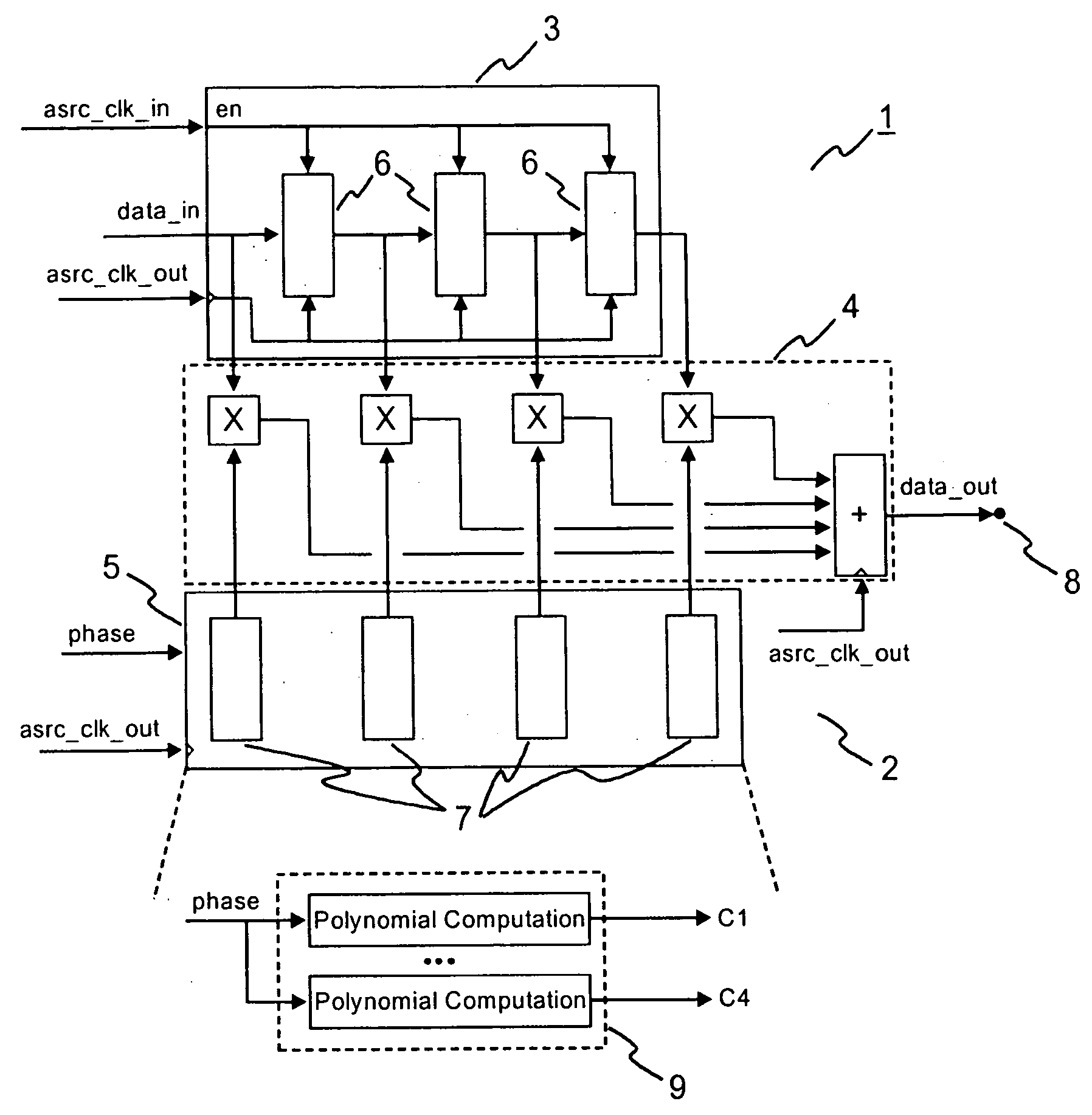
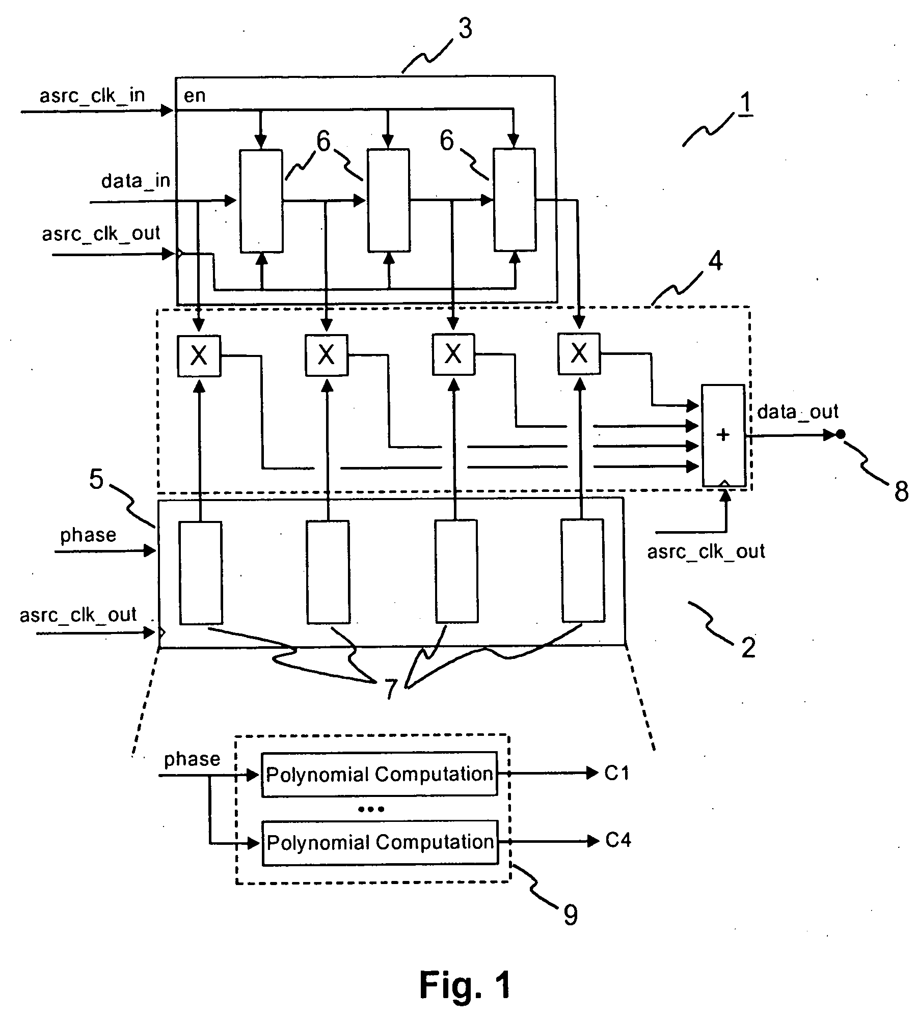
[0020]FIG. 1 schematically shows the ASRC 1 according to the invention. It comprises a 4-tap polyphase filter 2 which comprises a delay pipeline 3 and a digital signal processor (DSP) 4. The clock signal ascr_clk_in enables the delay pipeline 3 and clocks input data data_in sequentially through data registers (or flip-flops) 6, such that the utmost left register contains the newest sample, and the utmost right register the oldest sample.
[0021] The clock signal asrc_clk_in is in general a jittered clock because it is phase synchronous with asrc_clk_out and frequency synchronous with data_in. Typically this clock is generated by means of the DCO of a digital PLL. This DCO uses the same clock signal asrc_clk_out, which synchronizes all registers 6.
[0022] The ASRC 1 can be conveniently used when the input data data_in are represented by an oversampled signal. For the purposes of this disclosure an oversampled signal shall be understood to be a signal having a sample rate significantly...
PUM
 Abstract
Description
Claims
Application Information