System and method for maintaining air inflatable mattress configuration

a mattress and configuration technology, applied in the field of therapeutic beds and mattress systems and methods, can solve the problems of difficult to maintain the elevation of the patient off the mattress base over the entire surface of the mattress, undesirable and uncomfortable occurrences, and the like, and achieve the effect of improving the maintenance of an appropriate inflation profil

Active Publication Date: 2006-08-17
HUNTLEIGH TECH LTD
View PDF8 Cites 49 Cited by
  • Summary
  • Abstract
  • Description
  • Claims
  • Application Information

AI Technical Summary

Benefits of technology

[0016] (6) The overall mattress assembly, including the control systems and the methodologies associated with

Problems solved by technology

A number of problems are associated with inflatable air mattresses used in medical settings.
Likewise, when therapeutic variations in the pressure within the air mattress are implemented, it is often difficult to maintain the elevation of the patient off a mattress base over the entire surface of the mattress.
If, for whatever reason, the patient makes contact through the mattress surface with the more rigid mattress base, the result is the undesirable and uncomfortable occurrence that is referred to as “bottoming”.
In general, control systems that rely strictly on measurements of the pressure within an inflatable mattress fail to pr

Method used


Image

  • System and method for maintaining air inflatable mattress configuration
  • System and method for maintaining air inflatable mattress configuration
  • System and method for maintaining air inflatable mattress configuration

Examples


Embodiment Construction

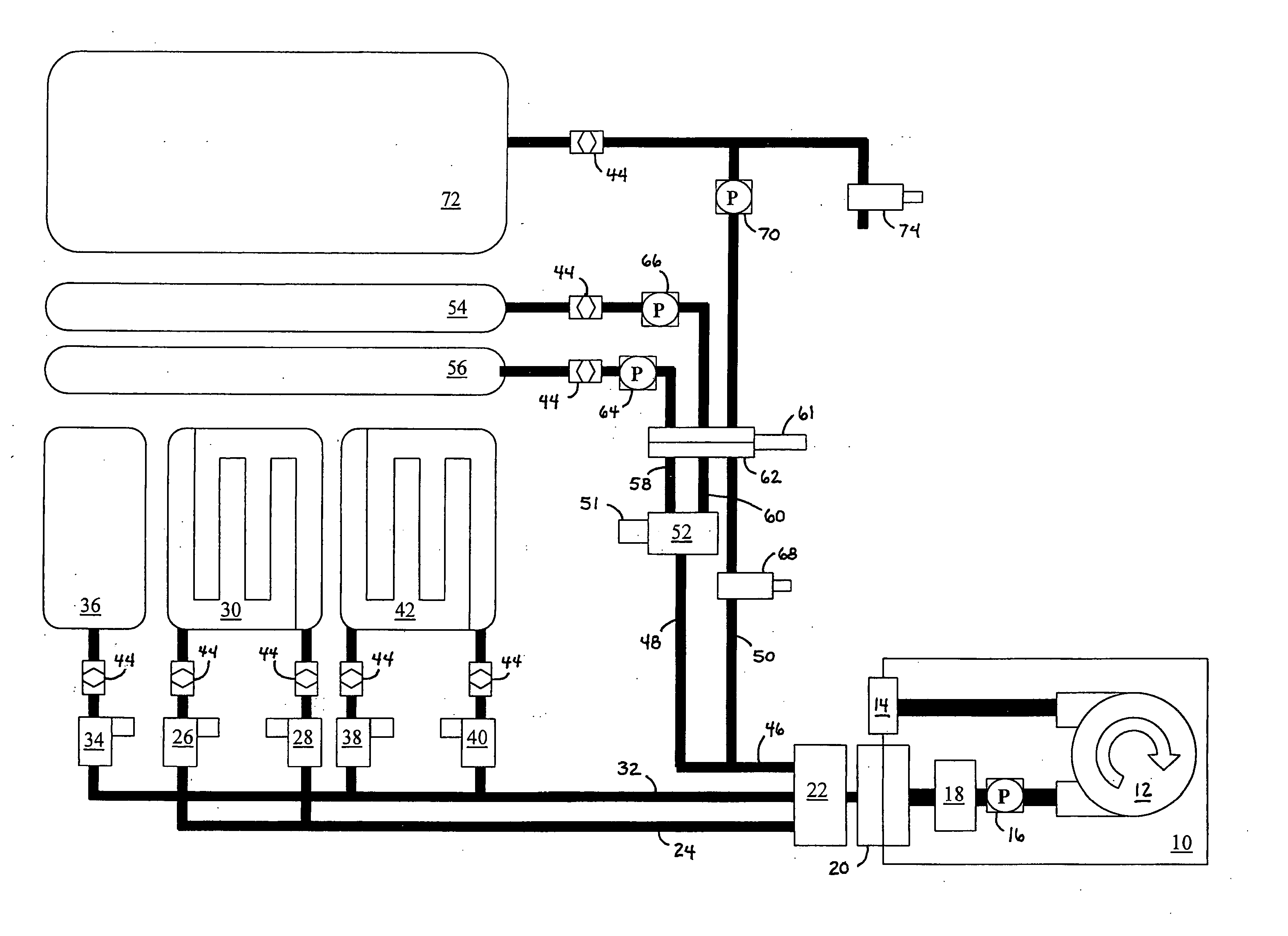
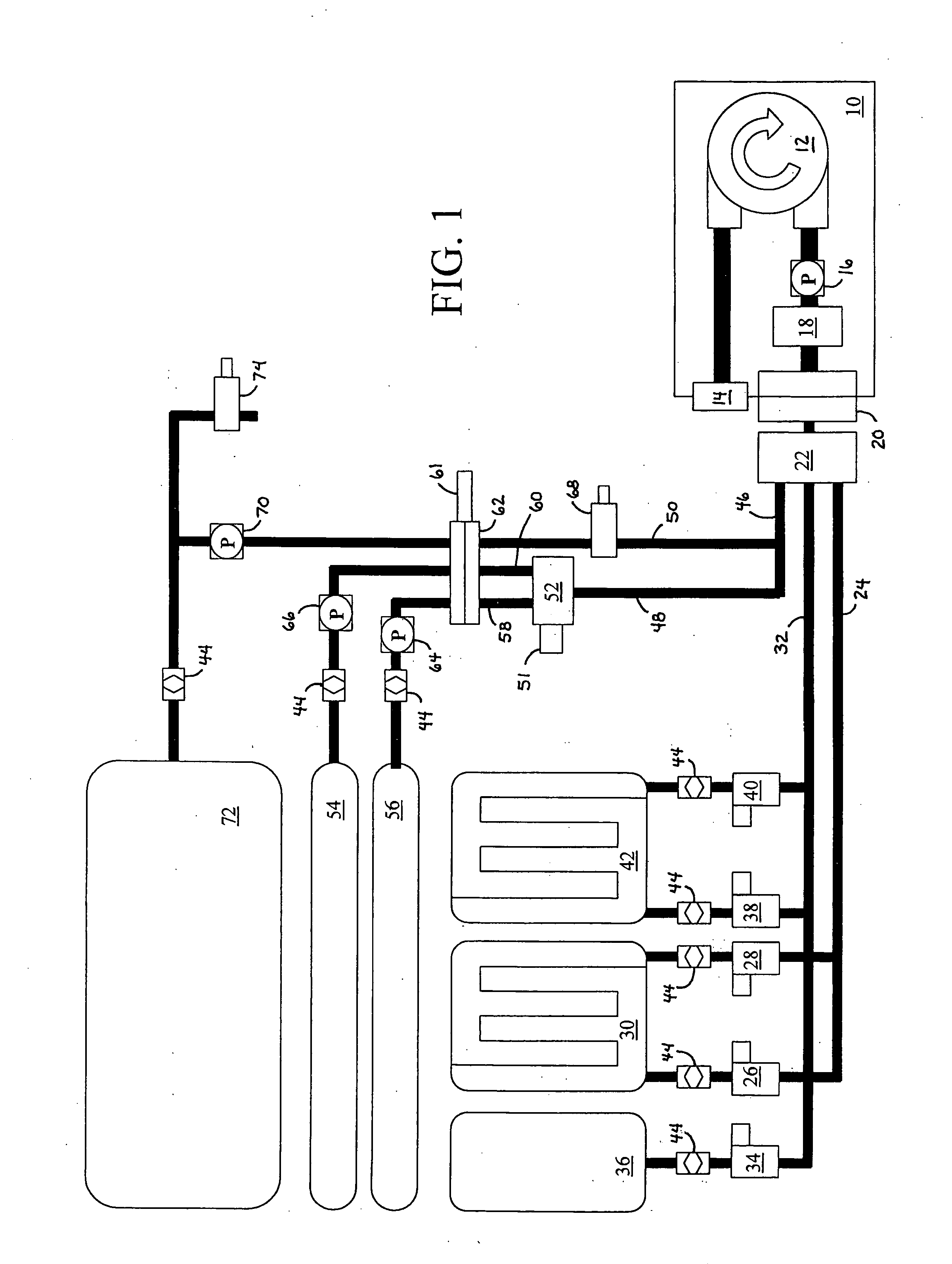
[0035] An overview of the system of the present invention may be discussed by reference to the schematic drawing shown in FIG. 1. In this overview of the system, the mattress components are shown in relation to and interconnected with the various control components of the system. In various embodiments, blower box 10 can be comprised of a blower fan 12 that incorporates a dust filter 14 on its intake and an output that incorporates a pressure transducer 16 and passes through a heater unit 18 before being passed into the conduits of the system. The output of the blower box 10 is established through hose connector 20 that incorporates a manifold of air connections as well as electrical connections (not shown) in the same connector unit (described in more detail below). In various embodiments, hose connector 20 can be single piece or multi-piece connector and can include a number of components, such as springs, latches, and the like. Hose connector 20 mates with and connects to distrib...


PUM


Abstract

A system and method for maintaining an air inflation mattress configuration sufficient for patient support and comfort. Infrared illumination levels are measured within individual or groups of inflated mattress chambers. A staggered approach to illumination monitoring of chambers or sections to eliminate crosstalk between the infrared sensors is carried out. Distributed microprocessor controllers established in a network configuration utilizing controller network protocols reduces the wiring and connections necessary for the assembled system. Various mattress cushion construction techniques, such as sewing and or RF welding methods, are used for the creation of individual chambers utilizing specific types of IR translucent, transparent or reflective materials. The construction of the cushions and bladders in the system includes the use of various types of fabrics with low to high air loss qualities as required. The overall mattress assembly, including the control systems and the methodologies associated with such control systems, provide a unique approach to the maintenance of a consistently comfortable patient support surface. The use of a handheld unit for both programming the system and downloading information about the operation of the system is also anticipated. The specific cushion construction designs associated with the head, body, and foot cushion components of the mattress are tailored to operate specifically with the control capabilities (sensors and air flow regulators) of the invention.

Description

CROSS-REFERENCE TO RELATED APPLICATION [0001] This application claims the benefit under 35 U.S.C. § 119 (e), of copending U.S. Provisional Application No. 60 / 653,303, filed Feb. 16, 2005.BACKGROUND OF THE INVENTION [0002] 1. Field of the Invention [0003] The present invention relates generally to therapeutic beds and mattress systems and methods for maintaining their function. The present invention relates more specifically to improved systems and methods for controlling the configuration and characteristics of an inflatable air mattress utilizing an array of networked sensors and control modules. [0004] 2. Description of the Related Art [0005] A number of problems are associated with inflatable air mattresses used in medical settings. Some such air mattresses are designed for therapeutic use and include high and low air loss fabric enclosures as well as control systems that alter the air pressure within the mattress in order to help reduce the occurrence of bed sores and similar de...

Claims


Application Information

Patent Timeline
IPC IPC(8): A47C27/10
CPCA61G7/05769A61G2203/40A61G2203/42A61G2203/46G16H40/63A47C27/10A47C27/08
Inventor PHILLIPS, BRUCE L.VRZALIK, JOHN H.PARKER, JEFFREY S.SMITH, KENNETH R.GONZALEZ, JUAN L.BENDELE, KEVIN W.OLIVA, MICHAEL R.SLIMPIN, PAUL D.LINA, CESAR Z.STACY, PETER CHARLESBEARD, MARK STEPHEN JAMESALEXANDER ROBSON, GODFREY CHARLES
Owner HUNTLEIGH TECH LTD
Why Eureka
Try Eureka