Automatic saw

a sawing machine and automatic technology, applied in the field of automatic sawing machines, can solve the problems of inability to move the piston reciprocally back, the inability of the switching valve to change the position of the switch valve, and the inability of the serrated blade to cut the workpiece, etc., to achieve the effect of reducing the inner diameter of the side opening, and facilitating us

Inactive Publication Date: 2006-08-17
S P ARI
View PDF6 Cites 4 Cited by
  • Summary
  • Abstract
  • Description
  • Claims
  • Application Information

AI Technical Summary

Benefits of technology

[0010] According to a preferred embodiment, the housing is capable of reducing an inner diameter of the side opening of an outer peripheral wall thereof by forming a slit at the outer peripheral wall extending in an axial direction from the side opening, and wherein, where coupled to the side opening, the motor housing is immobilized as an outer periphery of the motor housing is fastened to an inner surface of the side opening when the inner diameter of the side opening is reduced and is arranged as adjustable of a positional angle of the motor housing with respect to the axial direction of the serrate blade when the inner diameter of the side opening is widened.
[0011] The housing may secure a support placed by a side surface of the serrate blade to render impossible contact between a portion of the serrate blade placed by the support and a workpiece during cutting operation of the workpiece done by the serrate blade, and wherein a portion of the serrate blade to be in contact with the workpiece is adjustable by rendering the support movable in the axis direction of the serrate blade.
[0012] This invention thus structured can maintain the smooth back and forth reciprocal movement of the serrate blade for a long period of time by converting the rotational force of the crank shaft in association with the operation of the air motor into the back and forth reciprocal movement of the serrate blade via the engagement long hole and the engagement piece. Therefore, the automatic saw is free from unexpected stops of the cutting operation during use, can smoothly cut the workpiece with the serrate blade, and makes itself easily used. High quality automatic saws can be produced with easy assembling technique and lower costs because the saws are simply constituted solely from engagements of the engagement piece coupled to the serrate blade via the plunger and the crank shaft of the air motor.

Problems solved by technology

The switching valve, however, may fall in a situation that the back and forth movement correlative between the switching valve and the piston becomes impossible due to influences from frictional force or the like during repetitive reciprocal movement of the piston because the switching valve is inserted in the piston in being movable correlatively to each other.
Therefore, switching of opening and closing of both of the air introduction openings cannot be done, thereby rendering the piston impossible to move reciprocally back and forth, and thereby rendering the serrate blade impossible to cut the workpiece.
In such a case, the user manually shakes the automatic saw in the back and forth direction to revive the back and forth movement correlative between the switching valve and the piston and to allow the air introduction opening of the piston to be open and closed, and the user has to revive the back and forth reciprocal movement of the piston by introduction and exhaustion of air, so that such operation can be done not easily and reduces the workability.

Method used


Image

  • Automatic saw
  • Automatic saw
  • Automatic saw

Examples


Embodiment Construction

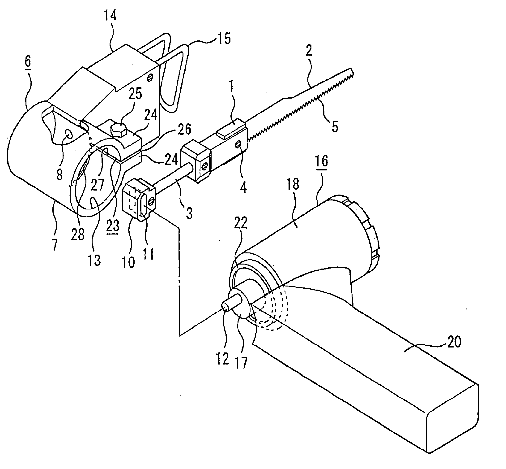
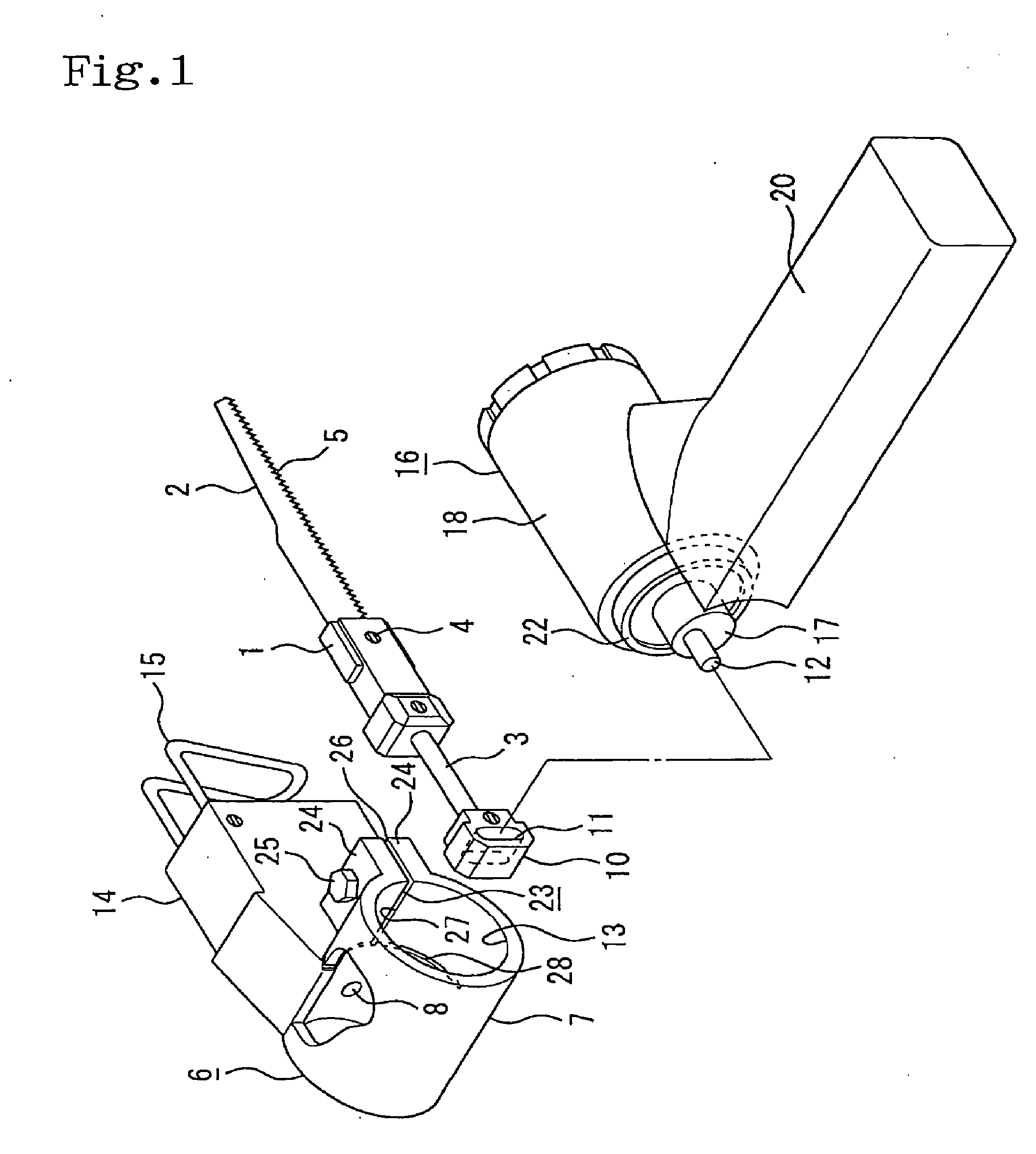
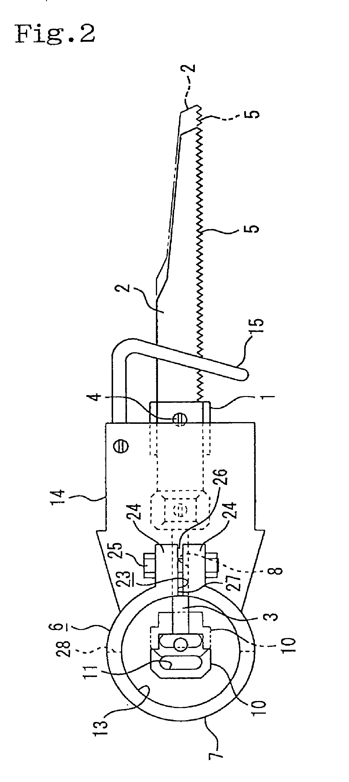
[0019] Hereinafter, with reference to the drawings, preferred embodiments according to the invention are described. FIG. 1 is an exploded perspective view showing an automatic saw; FIG. 2 is a plan view showing a housing, an engagement piece contained in the housing, and a serrate blade attached coupled to the engagement piece via a plunger; FIG. 3 is a perspective view showing the automatic saw in a usable state where a motor housing and the housing are coupled; FIG. 4 shows a state that the serrate blade can be placed with a proper angle to a grip of the motor housing held by the user where the motor housing and the housing are pivotally movable to as well as secured to each other; and FIG. 5 is a plan view showing a support movable in the back and forth reciprocal direction of the serrate blade.

[0020] In the drawings, the numeral 1 is a blade holder, and one end of the holder is coupled to a serrate blade 2 whereas the other end is securely coupled to a plunder 3 in a bar shape....


PUM

PropertyMeasurementUnit
rotational forceaaaaaaaaaa
inner diameteraaaaaaaaaa
frictional forceaaaaaaaaaa

Abstract

An automatic saw includes a serrated blade, a blade holder connected to the serrated blade at one end thereof, a plunger arranged at the other end of the blade holder and arranged inside a housing as slidable in the housing, an engagement piece secured to the plunger inside the housing having an engagement elongated hole formed at a side surface of the engagement piece, the engagement hole extending in a direction perpendicular to an extending direction of an axis of the plunger, an air motor rotatable of a crank shaft inserted in and engaged with the engagement hole via a side opening formed in the housing, and a motor housing covering the motor rotatably coupled to the side opening. The rotational force of the crank shaft according to operation of the air motor is converted to back and forth reciprocal movement of the serrated blade via the engagement hole and the engagement piece.

Description

BACKGROUND OF THE INVENTION [0001] 1. Field of the Invention [0002] This invention relates to an automatic saw in which a serrate blade is moved reciprocally in a back and forth direction by an air motor to cut a material to be cut, or a workpiece, such as a metal plate. [0003] 2. Description of Related Art [0004] Automatic saws utilizing electrically driven motors as set forth in, e.g., Japanese Patent Application Publications No. Heisei 6-198,601, and No. 2001-62627 have been known conventionally. Automatic saws utilizing air cylinders also exist. In such a product utilizing an air cylinder, the cylinder contains a piston movable back and forth in an axial direction of the serrate blade, and an air introduction route is arranged on the opposite ends of the cylinder via the piston. Air is alternatively introduced into the cylinder from the air introduction route to move the piston reciprocally back and forth in the axial direction of the serrate blade, thereby moving reciprocally b...

Claims


Application Information

Patent Timeline
Patent Type & Authority Applications(United States)
IPC IPC(8): B23D49/16B27B19/00B23D51/02B23D51/18B27B3/02
CPCB23D51/02B23D51/18
Inventor IZUMISAWA, OSAMU
Owner S P ARI
Why Eureka
Try Eureka