Method and device for the drilling of holes in ground or rocky material

Inactive Publication Date: 2006-08-17
ALWAG TUNNELAUSBAU GMBH
View PDF8 Cites 5 Cited by
  • Summary
  • Abstract
  • Description
  • Claims
  • Application Information

AI Technical Summary

Benefits of technology

[0006] To solve these objects, a method of the initially defined kind is essentially characterized in that the impact energy is transmitted from the drill rod assembly onto the impact shoe via an interposed impact ring and that the drill bit and optionally the impact ring are coupled with the drill rod assembly by a plug-in connection. Since the energy or impact energy is transmitted onto the drill bit separately and, in particular, centrally by the drill rod assembly and partially onto the envelope and/or jacket tubes via an impact shoe cooperating with the drill rod assembly, decoupling during the introduction of the drill bit from the envelope and/or the jacket tubes to be additionally introduced during the drilling procedure is feasible. It is, thus, enabled to limit the excavation or impact energy to be transmitted onto the drill bit to just the extent required for drilling, whereby the forces required for the introduction of the envelope and/or jacket tubes can, moreover, be taken into account separately from friction resistances optionally present between the outer peripheries of the envelope and/or jacket tubes and the borehole produced. By such decoupling of the drill bit from the envelope and/or jacket tubes for the introduction of the envelope and/or jacket tubes, it is not necessary, as opposed to known configurations, to introduce th

Problems solved by technology

That embodiment involves the drawback that also the energy required for the introduction of the envelope and/or jacket tubes causing, for instance, friction resistances by partially abutting on the borehole wall must be introduced via the drill bit.
That embo

Method used


Image

  • Method and device for the drilling of holes in ground or rocky material
  • Method and device for the drilling of holes in ground or rocky material
  • Method and device for the drilling of holes in ground or rocky material

Examples


Embodiment Construction

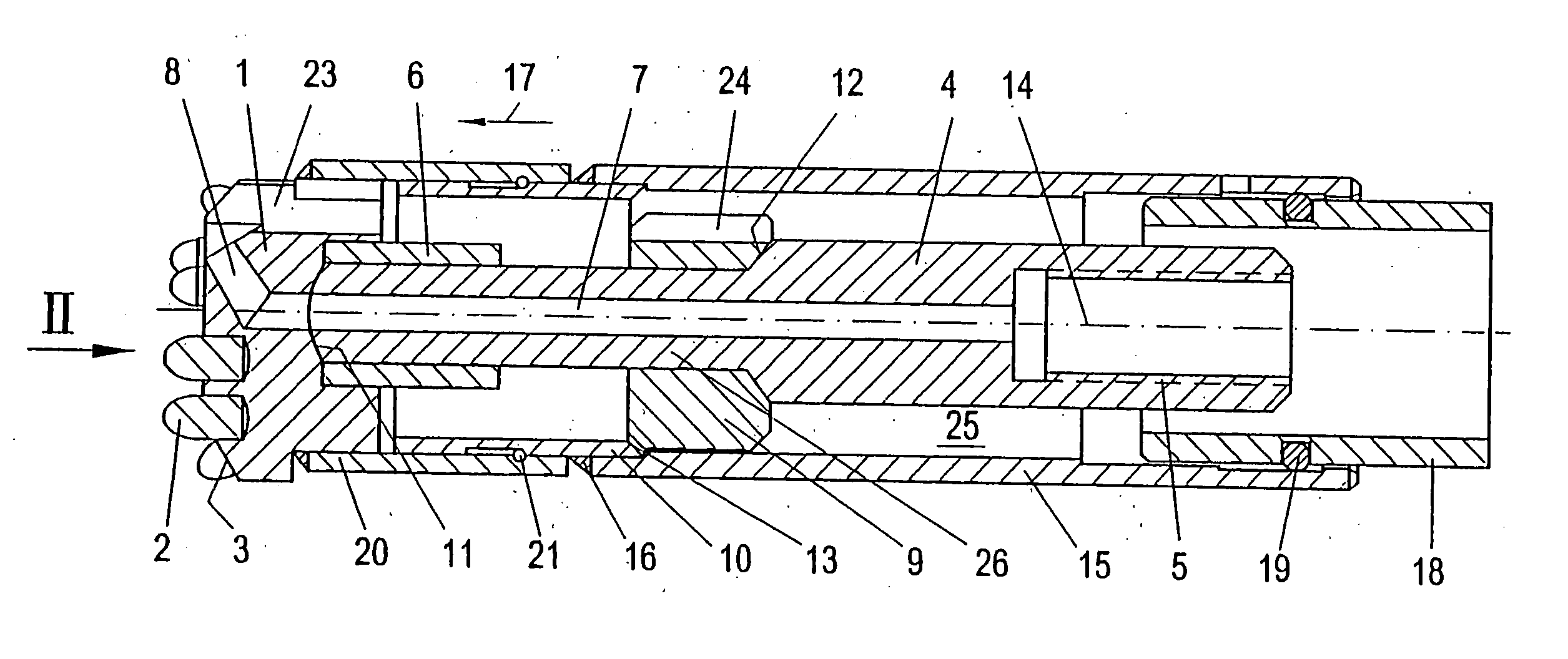
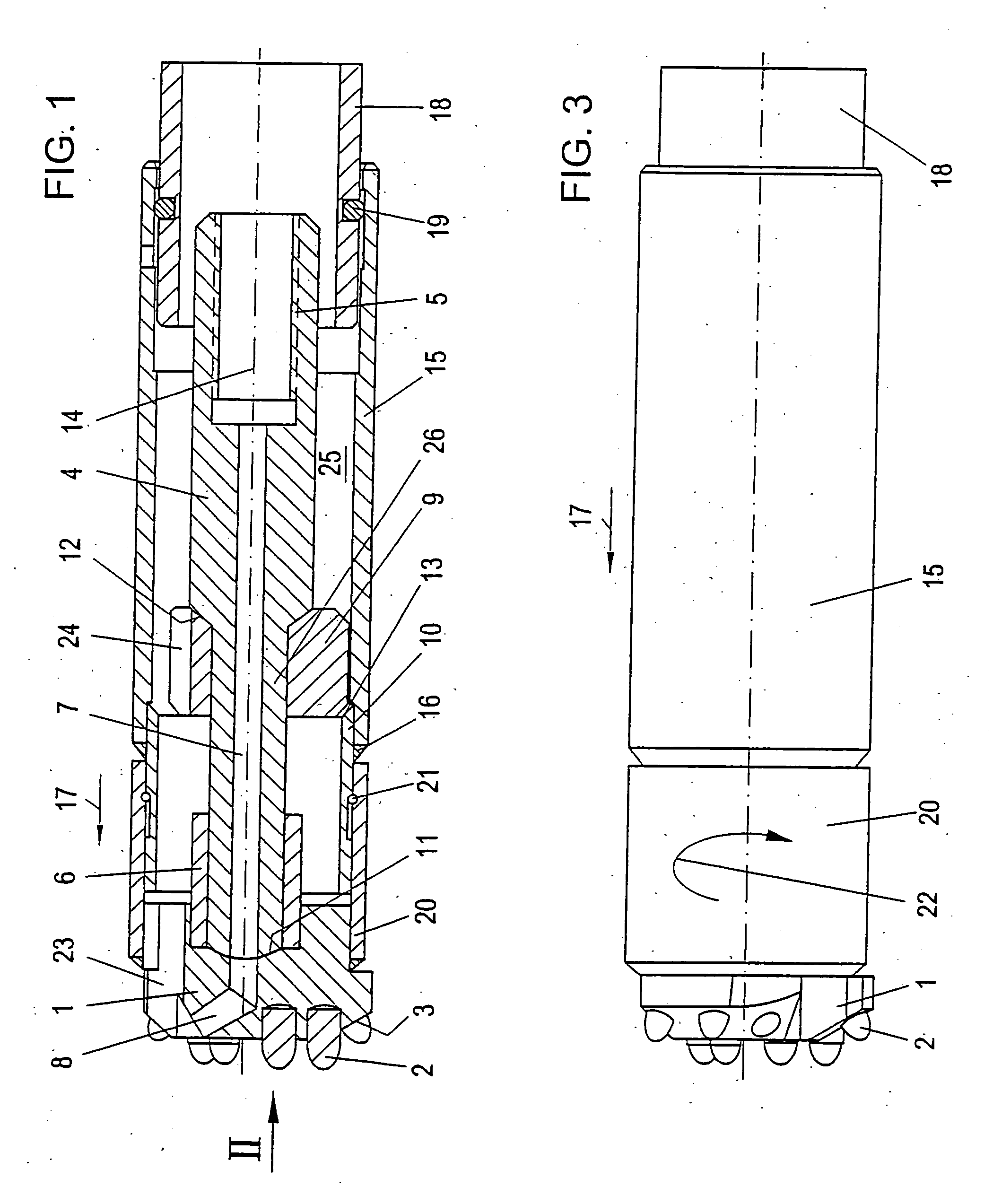
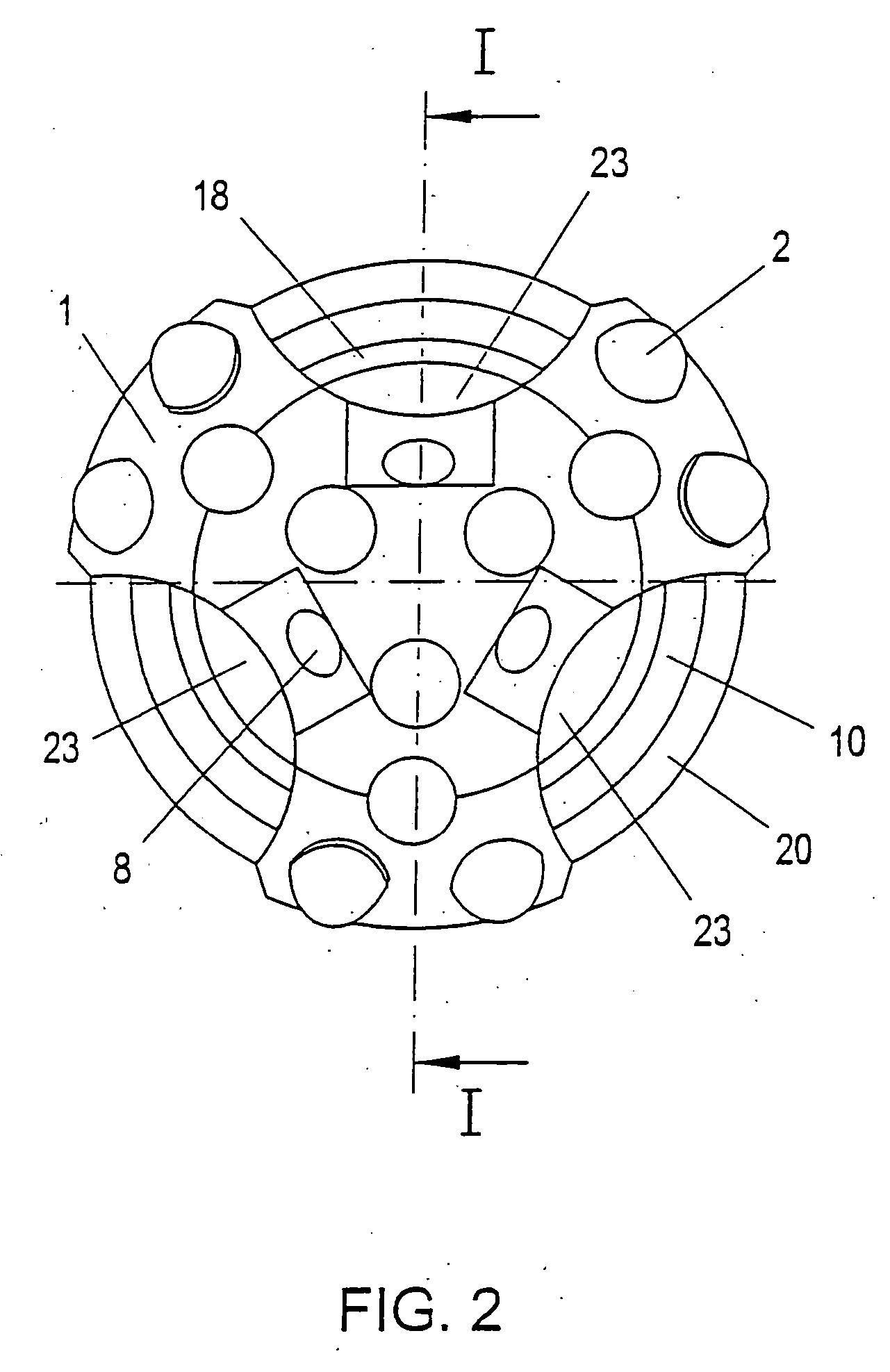
[0025] In the Figures, a drill bit is generally denoted by 1, which, in a manner known per se, comprises a plurality of hard-metal or hard-material inserts 2 for excavating material not illustrated in detail in order to form a borehole not illustrated in detail, either.

[0026] As is apparent from FIG. 1, the drill bit 1 is coupled with a drill rod assembly 4 on its side facing away from the working surface 3, FIG. 1 showing but the foremost section of the drill rod assembly 4, wherein the drill rod assembly 4, in a manner known per se, is accordingly extensible, for instance, via a screw connection indicated at 5. The drill rod assembly 4 substantially centrally in the region of a plug-in connection 6 cooperates directly with the drill bit 1, wherein FIG. 1, moreover, schematically indicates a flush channel 7 provided within the drill rod assembly 4 and running into respective flush openings 8 provided in the region of the working surface 3 of the drill bit 1.

[0027] In addition to ...


PUM


Abstract

In a method and device for drilling, in particular percussion drilling or rotary percussion drilling, holes in soil or rock material, wherein a borehole is formed by a percussive and/or rotational movement carried out by a drill bit (1) mounted on a drill rod assembly (4) and an envelope tube and/or a jacket tube (15, 18) is introduced into the borehole, it is provided that the impact energy introduced by the drill rod assembly (4) is transmitted partially, particularly centrally, by the drill rod assembly (4) onto the drill bit (1) and partially via an impact shoe (10) cooperating with the drill rod assembly (4) onto the envelope and/or jacket tubes (15, 18), thus enabling the reliable introduction of the excavation or impact energy into the drill bit (1) as well as into the envelope and/or jacket tubes (15, 18).

Description

FIELD OF THE INVENTION [0001] The present invention relates to a method for drilling, in particular percussion drilling or rotary percussion drilling, holes in soil or rock material, wherein a borehole is formed by a percussive and / or rotational movement carried out by a drill bit mounted on a drill rod assembly and an envelope tube and / or a jacket tube is introduced into the borehole, wherein the impact energy introduced by the drill rod assembly is transmitted partially, particularly centrally, by the drill rod assembly onto the drill bit and partially via an impact shoe cooperating with the drill rod assembly onto the envelope and / or jacket tubes. The invention further relates to a device for drilling, in particular percussion drilling or rotary percussion drilling, holes in soil or rock material, wherein a borehole is formed by a percussive and / or rotational movement carried out by a drill bit mounted on a drill rod assembly and an envelope tube and / or a jacket tube is capable o...

Claims


Application Information

Patent Timeline
IPC IPC(8): E21B7/00E21B1/00E21B7/20
CPCE21B1/00E21B7/20E21B1/26E21B6/02
Inventor MOCIVNIK, JOSEFEGGER-MOCIVNIK, RENE
Owner ALWAG TUNNELAUSBAU GMBH
Why Eureka
Try Eureka