
Gravure paper and manufacturing process for this paper

a technology of gravure paper and manufacturing process, which is applied in the field of gravure paper manufacturing process, can solve the problems of high filler content, high beating degree, and inability to meet the requirements of high paper strength,

Inactive Publication Date: 2002-07-23
VOITH PATENT GMBH
View PDF18 Cites 13 Cited by
  • Summary
  • Abstract
  • Description
  • Claims
  • Application Information

AI Technical Summary

Benefits of technology

Because of the composition of the pigment and / or filler slurry, there is also the possibility of applying this to the fibrous material web through a wire. This advantageously allows the coating to be applied to the paper web at a time at which the tear strength of the paper web itself is not yet sufficient to remove it from the wire. Even if this were possible, the coating process would have a straining action on the fiber structure and would impair the later tear strength of the paper web. The application of the pigment and / or filler slurry can also take place through a wire and onto a paper web which is already relatively tear-resistant in order to reduce the potential of a possible web tear in the manufacturing process and therefore in order to increase the effective running time of the paper machine.
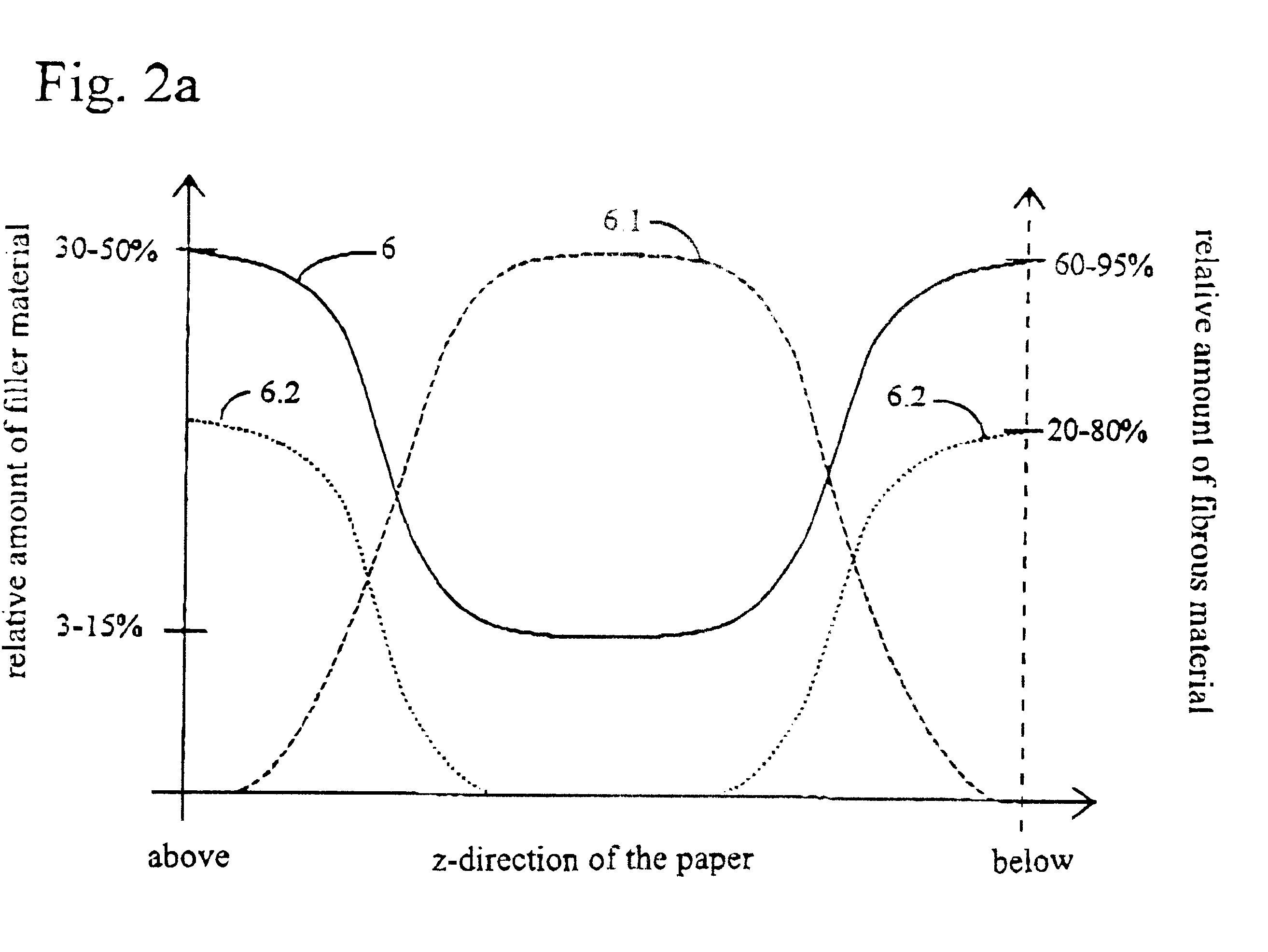
This process according to the invention also achieves the fact that in the outer layer to be printed or in the two outer layers, there is a very high filler and / or pigment content while, in the one fiber-containing layer, or in the inner layer, there are fibers with a relatively low beating degree that corresponds to greater than approximately 50 ml CSF, and preferably in the range from approximately 50 ml to approximately 100 ml CSF, so that a very favorable tear strength of the paper web is assured here.
On the one hand, gravure paper manufactured in this way fulfills the requirement for a very favorable printability by utilizing the high filler content in at least one or also in both of the outer layers, and on the other hand, has a very closed, homogeneous, and flat surface. Furthermore, the runability of such a gravure paper is advantageously improved to a significant degree, such that, at the same time, due to the low beating degree required, a considerable energy savings is achieved in the manufacture of the stock used and therefore of the fibrous suspension. The gravure paper has particularly favorable properties if, after the application of the pigment and / or filler slurry onto the unfinished web, a passage through a press occurs, since a high degree of bonding of the pigment and / or filler layer to the fibrous material web is achieved thereby.
The advantage of a gravure paper produced in this manner lies essentially in the extraordinarily more favorable energy requirement in the manufacture of the fibrous material suspension and an outstanding printability of the paper surface due to its high filler content. Since the investment in an additional coating machine can be eliminated, this is a very cost-effective manufacturing possibility.

Problems solved by technology

However, a high filler content runs counter to the requirement for a high strength of the paper.
In order to achieve a high tear strength, an excessive filler content is not desirable since the filler acts as an obstacle to the hydrogen bridge formation between the fibers of the paper.
In addition, a high beating degree impairs the strength due to a fiber-shortening effect.
However, this requires a high investment outlay because, in addition to the paper machine required for producing the paper, an investment must also be made in a coating machine, which may function either on-line or off-line in relation to the paper manufacturing process.
However, this is very energy intensive since the energy used rises exponentially as the beating degree increases.
As a result, it is necessary to use higher quality and therefore more expensive fibrous material components.
Even if this were possible, the coating process would have a straining action on the fiber structure and would impair the later tear strength of the paper web.

Method used


Image

  • Gravure paper and manufacturing process for this paper
  • Gravure paper and manufacturing process for this paper
  • Gravure paper and manufacturing process for this paper

Examples


Embodiment Construction

The particulars shown herein are by way of example and for purposes of illustrative discussion of the embodiments of the present invention only and are presented in the cause of providing what is believed to be the most usefull and readily understood description of the principles and conceptual aspects of the present invention. In this regard, no attempt is made to show structural details of the present invention in more detail than is necessary for the fundamental understanding of the present invention, the description taken with the drawings making apparent to those skilled in the art how the several forms of the present invention may be embodied in practice.

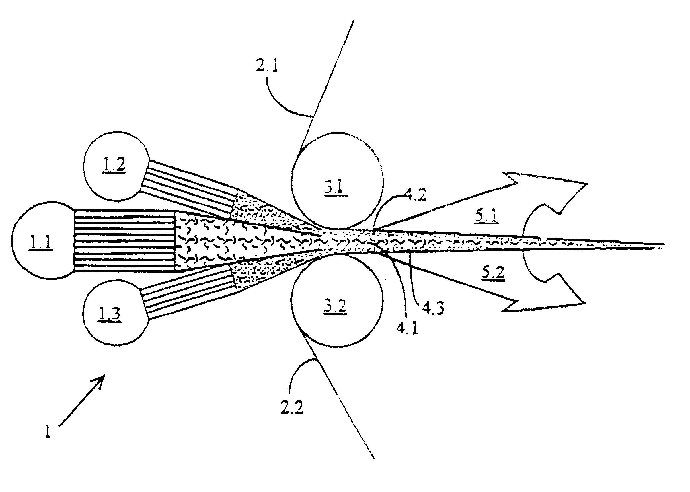
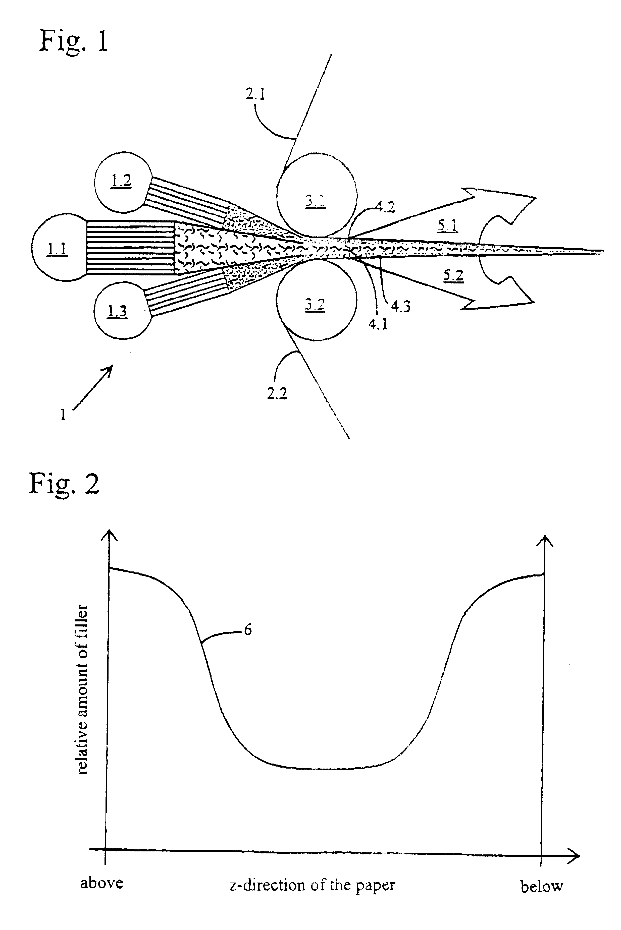
FIG. 1 shows the manufacturing process according to the invention, with a three-layer headbox 1 and an adjoining twin-wire former. The headbox 1 has three supplies 1.1 to 1.3. with the middle supply 1.1 being loaded with a stock suspension produced according to the invention with a stock that has a beating degree that is great...


PUM

PropertyMeasurementUnit
roughnessaaaaaaaaaa
surface roughnessaaaaaaaaaa
roughness depthaaaaaaaaaa

Abstract

A gravure paper and a method of manufacturing gravure paper having a maximal roughness depth of approximately 1.40 mum. The method utilizes a paper machine including a forming system, a first press section, and a drying section, and includes producing a stock suspension including a stock having a freeness of greater than or equal to approximately 50 ml CSF, forming an unfinished fibrous material web from the stock suspension, and applying at least one of a pigment and a filler slurry to the unfinished fibrous material web between a beginning of the forming system and a position at which the dry matter content of the unfinished fibrous material web is approximately <=90%.

Description

The present application claims priority under 35 U.S.C. .sctn.119 of German Patent Application No. 199 22 390.4, filed on May 14, 1999, the disclosure of which is expressly incorporated by reference herein in its entirety.1. Field of the InventionThe invention relates to a manufacturing process for a gravure paper with a maximal roughness depth of approximately 1.40 .mu.m (measured with the "Parker Print Surf" method according to DIN-ISO 8791-4). The invention also relates to a gravure paper which is manufactured in a single work cycle.2. Discussion of Background InformationDifferent printing processes are known from the prior art which place different demands on the quality and properties of the paper to be printed in order to achieve an optimal printing quality. In the gravure process, it is particularly crucial that the surface of the paper used is very smooth or has a very low roughness depth so that a sufficient printing quality is achieved, Furthermore, the porosity must be lo...

Claims


Application Information

Patent Timeline
Patent Type & Authority Patents(United States)
IPC IPC(8): D21F11/04D21F11/00D21H19/84D21H19/00D21F9/00D21H23/00D21H23/54D21H23/28
CPCD21F9/006D21F11/04D21H19/84D21H23/28D21H23/54
Inventor MENDEZ-GALLON, BENJAMINPRECHTEL, KLAUSSTURM, WOLFRAMMOSER, JOHANNSCHMIDT-ROHR, VOLKERCEDRA, INGOLF
Owner VOITH PATENT GMBH
Learn More