Device and method for optical control under diffuse illumination and observation means of crockery items or any glazed ceramic products

a technology of optical control and diffuse illumination, which is applied in the direction of material analysis, geological measurements, instruments, etc., can solve the problems of not being able to provide inspection that is sufficiently high-performance and multi-purpose, not being able to meet the required detectivity, and no prior art system has been designed for pieces, etc., to achieve the effect of higher detectivity

Inactive Publication Date: 2006-08-17
OPTOMACHINES
View PDF8 Cites 25 Cited by
  • Summary
  • Abstract
  • Description
  • Claims
  • Application Information

AI Technical Summary

Benefits of technology

[0052] A major advantage of the invention is that it makes it possible to implement both options in a, single item of equipment, which offers obvious industrial advantages.
[0053] The first option (overall diffuse illumination of the piece) produces a reflected image of medium tone, making it possible to reveal well certain types of defects, while the second option (localized illumination of at least a portion of the piece by at least one localized of diffuse illumination) makes it possible to bring closer the light / shade limit of the defect to be detected, and to obtain higher detectivity; this makes it possible to detect defects that are very difficult to detect, in particular, pinholes in the glazing or “shallow-sloping” depressions in the glazing, and the like.
[0054] In a particular embodiment, observation is optionally also performed by accessory means such as means delivering glancing illumination, and mirrors for reflecting at least a portion of the image of the product, in particular the image of one or more portions that are not risible to the main observation means because they are masked, e.g. by the product itself.
[0055] In a first preferred alternative of the invention, the method is performed in two stages.
[0056] In another alternative, the method is performed in two or more stages, typically with a plurality of successive illumination sequences.
[0057] In a second alternative of the invention, the method is performed in one stage only, by using additional optical multiplexing means.

Problems solved by technology

Thus, diffuse illumination systems are commercially available that are designed for small shiny pieces, using semi-reflective strips or integration spheres, but in different configurations, and that, in addition to an unsuitable scale factor, do not make it possible to provide inspection that is sufficiently high-performance and multi-purpose, and that satisfies the acute technical problem posed.
Such systems were not designed to inspect pieces of crockery that are relatively large in size and that are concave or convex to various extents, and are unsatisfactory as regards the required detectivity.
Thus, no system of the prior art has been designed for pieces of crockery and the like, quality control currently still being performed by visual inspection by operators who are specially trained, but who are subject to errors or to tiredness, and whose inspection throughput is limited.

Method used


Image

  • Device and method for optical control under diffuse illumination and observation means of crockery items or any glazed ceramic products
  • Device and method for optical control under diffuse illumination and observation means of crockery items or any glazed ceramic products
  • Device and method for optical control under diffuse illumination and observation means of crockery items or any glazed ceramic products

Examples


Embodiment Construction

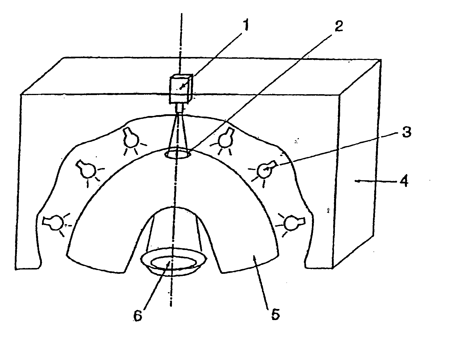
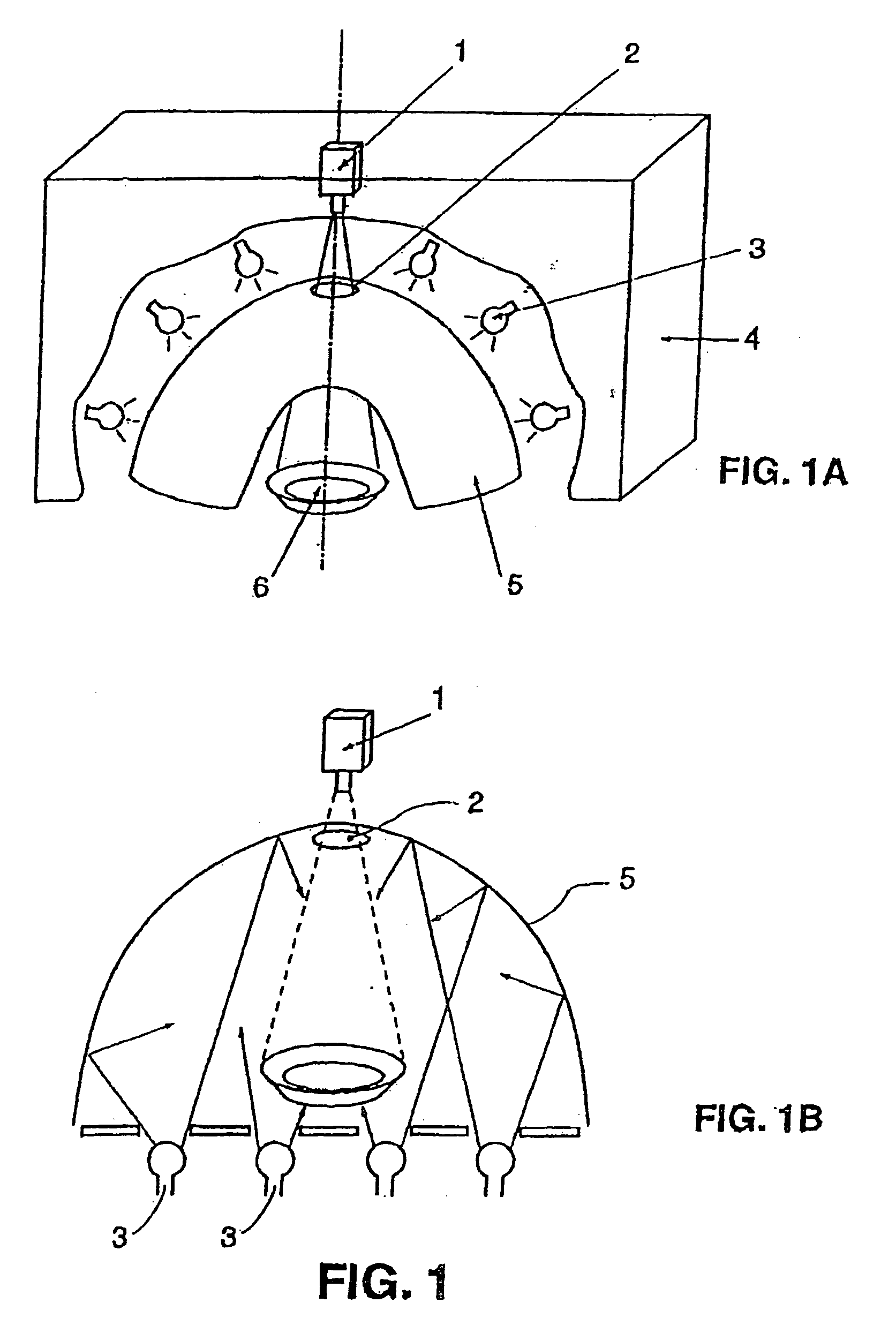
[0081] Accompanying FIG. 1A, which shows the overall diffuse lighting option, with, in this example, light sources uniformly distributed above a dome, shows that the pieces 6 pass under a translucent dome 5 that diffuses by transmission the light emitted by light sources 3 placed outside.

[0082] The diffused light is reflected by the piece, in particular towards the camera 1 through a suitable orifice 2 provided in the dome facing the camera. The resulting assembly is encased by a hood 4. The means for causing the pieces to advance under the dome are not shown. Only the inlet orifice is shown (an outlet orifice naturally exists in the direction of advance of the pieces).

[0083] Accompanying FIG. 1B shows the same configuration as FIG. 1A except that the light sources are placed under the dome and that the light is diffused by a, white opaque dome, by being reflected towards the piece.

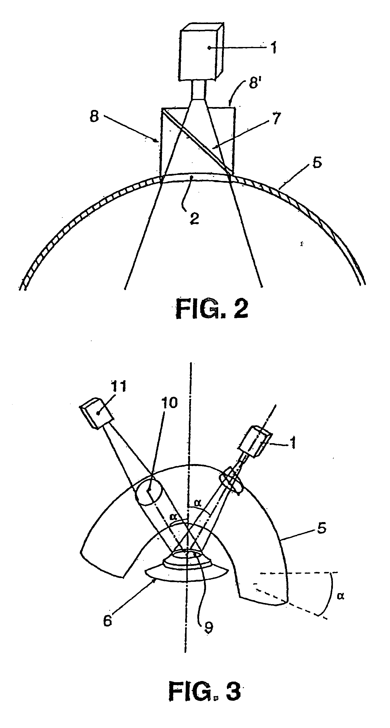
[0084] In FIG. 2, the apparatus is as shown in FIG. 1, except that a semi-reflective strip 7 is ins...


PUM

PropertyMeasurementUnit
temperaturesaaaaaaaaaa
distanceaaaaaaaaaa
frequenciesaaaaaaaaaa

Abstract

In the present invention, a method and apparatus are implemented for inspecting the surfaces of ceramic tableware / pieces of ceramic crockery, said method and apparatus being characterized in that, with a single item of equipment: A—the product is illuminated by overall or zone-by-zone diffuse illumination; and B—the product is observed using one or more observation means, by causing the overall diffuse illumination or the localized diffuse illumination from at least one diffuse illumination zone adapted to make at least a selected portion of the product shiny to reflect off said product towards said one or more observation means. The invention makes it possible, with a single piece of apparatus, to show and to identify the defects, whatever they may be, using methods that are “multi-purpose” and fully effective even in critical cases, such as a combination of complex shapes, of shininess, and of white-on-white defects, unlike the prior art.

Description

CROSS-REFERENCE TO RELATED APPLICATIONS [0001] This application is a Continuation of application Ser. No. 10 / 221,736 filed Dec. 18, 2002, the disclosure of which is incorporated herein by reference in its entirety.BACKGROUND OF THE INVENTION Field of the Invention [0002] Current State of the Art [0003] Inspecting appearance by industrial viewing is an activity that is undergoing development in certain industries. The techniques and the equipment are developed and specialized to various extends depending on the size of the corresponding markets. [0004] In the ceramic industry in the broadest sense, developments have been made and equipment is available on the market for certain products such as wall or floor tiles, and, to a lesser extent, roof tiles. [0005] To date, on the market, there is no equipment for automatically inspecting crockery, i.e. plates, cups, serving dishes, coffeepots, teapots, vases, etc. [0006] And yet, the proportion of the pieces leaving the kiln that have defe...

Claims


Application Information

Patent Timeline
Patent Type & Authority Applications(United States)
IPC IPC(8): G01N21/86G01V8/00G01N21/88
CPCG01N21/8806G01N21/9036G01N21/909G01N2021/8812
Inventor PARADIS, FRANCOIS
Owner OPTOMACHINES
Why Eureka
Try Eureka