Rotary cam alignment system

a technology of rotary cams and alignment systems, which is applied in the direction of resilient suspensions, vehicle springs, vehicle components, etc., can solve the problems of increasing simple and low-cost, and achieves simple and low-cost methods, less time, and increased the load capacity of the alignment mechanism

Inactive Publication Date: 2006-08-17
HENDRICKSON USA L L C
View PDF6 Cites 16 Cited by
  • Summary
  • Abstract
  • Description
  • Claims
  • Application Information

AI Technical Summary

Benefits of technology

[0009] A suspension in accordance with the present invention has several advantages as compared to conventional suspension systems. First, the inventive system does not require the installation or removal of welds during the alignment process and, therefore, requires less time for realignment of the suspension as compared to many conventional systems. Second, the use of a bushing in one embodiment of the inventive system increases the load capacity of the alignment mechanism. Third, the inventive system is lightweight and uses simple, low-cost methods to manufacture components of the inventive system. As a result, the inventive system weighs less than most conventional systems and is less costly.

Problems solved by technology

Second, the use of a bushing in one embodiment of the inventive system increases the load capacity of the alignment mechanism.
Third, the inventive system is lightweight and uses simple, low-cost methods to manufacture components of the inventive system.

Method used


Image

  • Rotary cam alignment system
  • Rotary cam alignment system
  • Rotary cam alignment system

Examples


Embodiment Construction

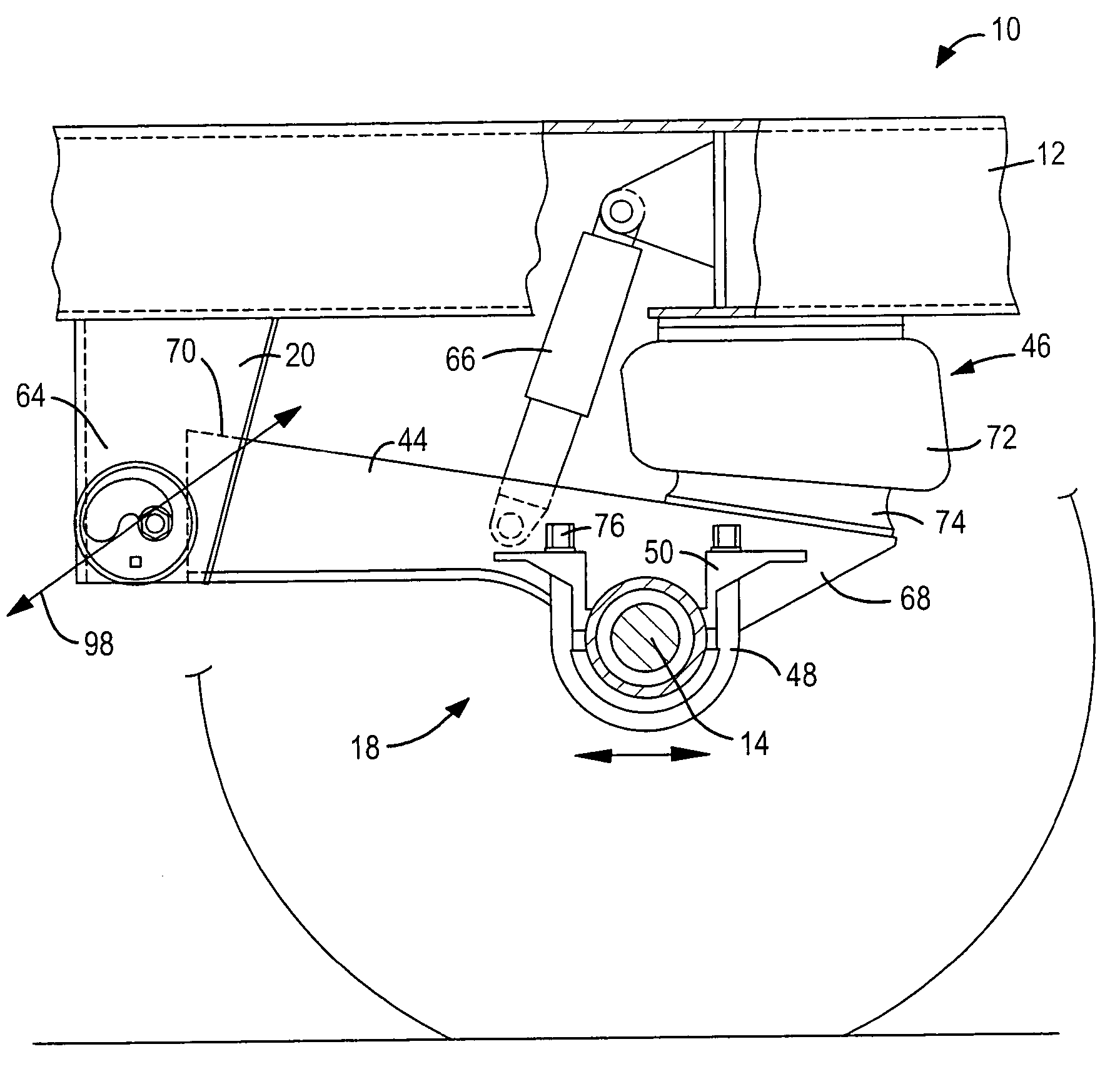
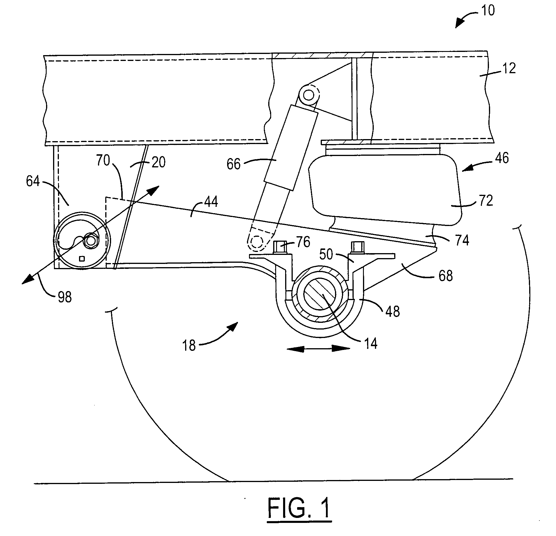
[0014] Referring now to the drawings wherein like reference numerals are used to identify identical components in the various views, FIG. 1 illustrates a portion of a vehicle 10. Vehicle 10 may include a frame 12, one or more axles 14, wheels 16, and a suspension 18 in accordance with the present invention. In the illustrated embodiment, vehicle 10 comprises a semi-trailer. It should be understood, however, that the present invention may find application in a wide variety of vehicles.

[0015] Frame 12 provides structural support to the body of vehicle 10. Frame 12 is conventional in the art and may be made from conventional metals and metal alloys such as steel. Frame 12 may include a pair of longitudinal rails (only one of which is shown in FIG. 1) and cross-members as is conventional in the art. Frame 12 may also include a plurality of mounting brackets, such as bracket 20, for mounting various components of vehicle 10 including suspension 18.

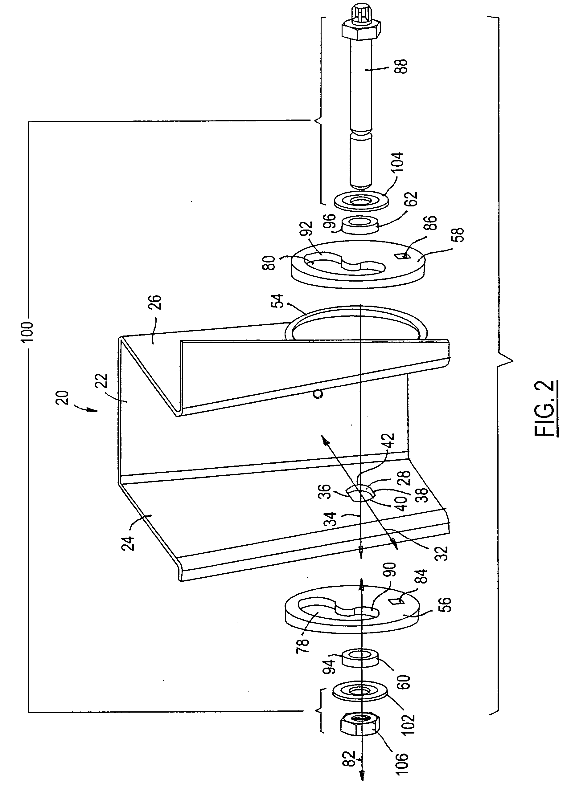
[0016] Referring to FIG. 2, bracket 20...


PUM


Abstract

An improved system used for alignment of a vehicle suspension and axle includes a cam plate that is rotatable relative to one of two spaced plates of a hanger bracket about an axis of rotation extending through a center of the cam plate. An aperture in the cam plate is aligned with an elongated opening in the bracket plate and defines a cam surface. A bushing may be disposed in the aperture and ride on the cam surface. A fastener extends through the bushing, the elongated openings in the bracket plates, and the suspension control arm. Rotation of the cam plate and movement of the bushing and the fastener along the cam surface of the aperture displaces the fastener along the elongated openings of the bracket.

Description

BACKGROUND OF THE INVENTION [0001] 1. Field of the Invention [0002] This invention relates to vehicle suspensions and, in particular, to a system used for alignment of a vehicle suspension and axle. [0003] 2. Disclosure of Related Art [0004] In a conventional vehicle suspension system, a suspension control arm has a first end rigidly connected to an axle of the vehicle and a second end pivotally connected to a bracket descending from the vehicle frame. The second end of the control arm may terminate in a bushing. The bracket generally includes first and second spaced walls that receive the bushing therebetween. A fastener extends through the first wall of the bracket, through the bushing, and through the second wall of the bracket. The fastener may also extend through one or more washers disposed on either side of the bushing between the first and second walls of the bracket. A nut is used to secure the fastener in place relative to the bracket and the control arm pivots about the f...

Claims


Application Information

Patent Timeline
Patent Type & Authority Applications(United States)
IPC IPC(8): B62D17/00B60G9/00
CPCB60G7/008B60G7/02B60G9/003B60G2200/31B60G2202/152B60G2204/143B60G2204/42B60G2204/61
Inventor ZEBOLSKY, MICHAEL L.
Owner HENDRICKSON USA L L C
Why Eureka
Try Eureka