[0014] Since many years red, green and yellow LED are used for electronic devices e.g. as indicators or the red LED for mobile battery chargers. The present invention preferably uses white LED for providing an illuminating
system. Contrary to the common practice, the present invention provides a mirror unit using at least one white LED having a size and a
power consumption better than the prior art
bulb systems. Correspondingly, the same
luminosity level compared to the prior art is realized by one third in
current consumption by the present invention. Further, said LED are almost ten times smaller than said bulbs. According to a preferred embodiment of the present invention, a
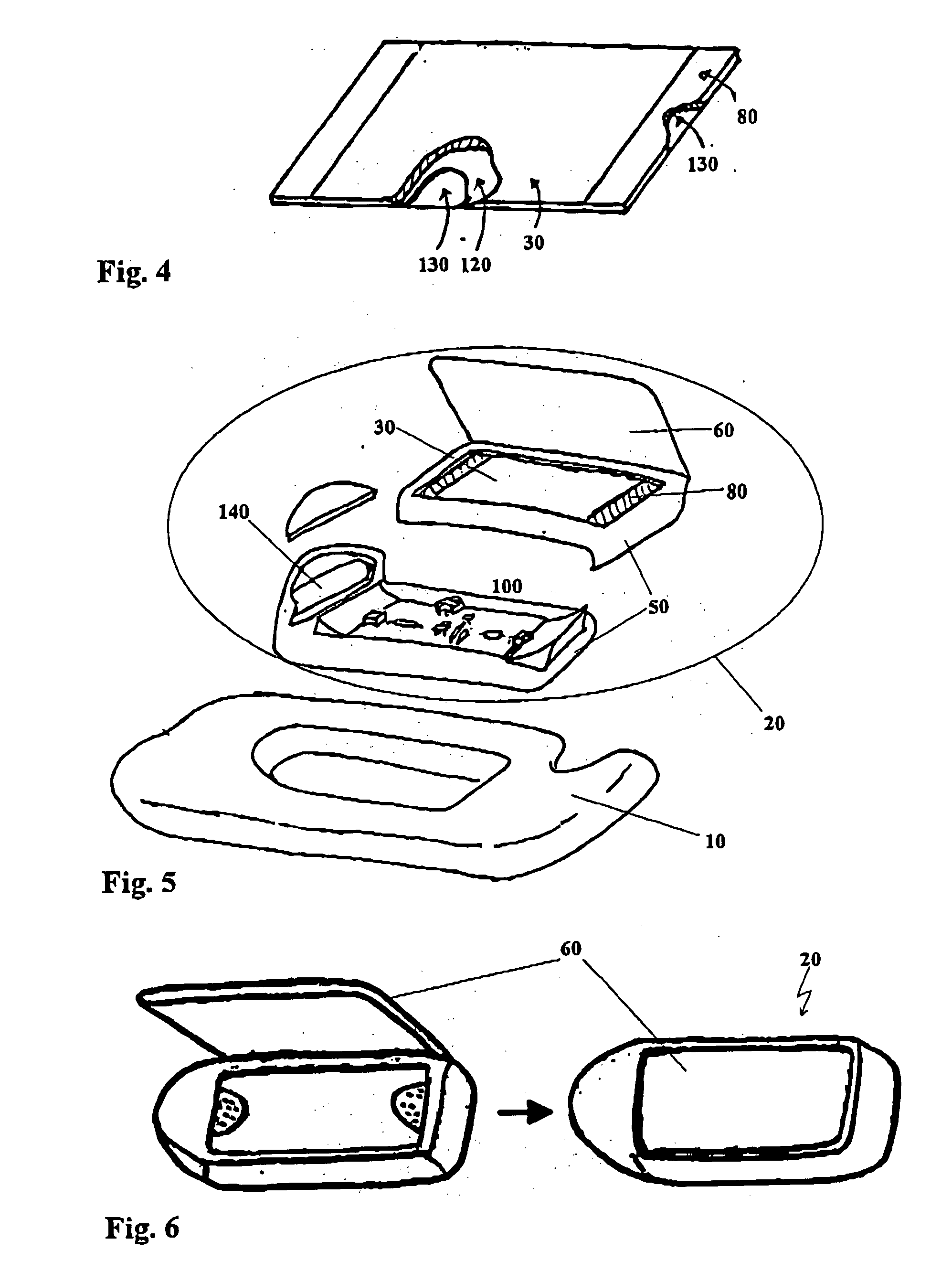
printed circuit board is used for controlling said LED which guarantees a space saving design. In view of the generally used metallic components for controlling said illumination means, said
printed circuit board can be equipped with different configurations to provide extra services without changes in construction of said mirror unit. Accordingly, expensive procedure steps saved during production of mirror units having different technical features.
[0015] Using light-emitting diodes in accordance with the invention guarantees low
power consumption, heat development so low that it can be neglected, and little spatial requirements in comparison with common illumination means, such as e.g. incandescent bulbs. At the same time, the
luminous intensity produced by the light-emitting diodes is sufficient for using them as illumination means of the mirror unit. Further, the light-emitting diodes do not have to be covered necessarily with a lens as is the case with common illumination means. This results in an advantageous
assembly of the mirror unit from less individual elements, resulting in a simplified and cheaper production of the mirror unit.
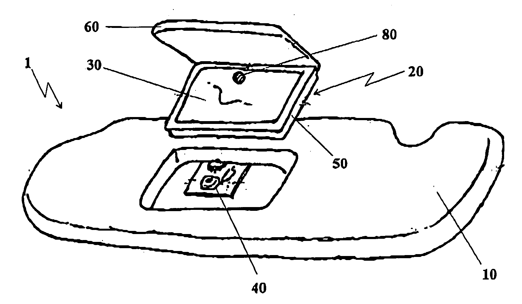
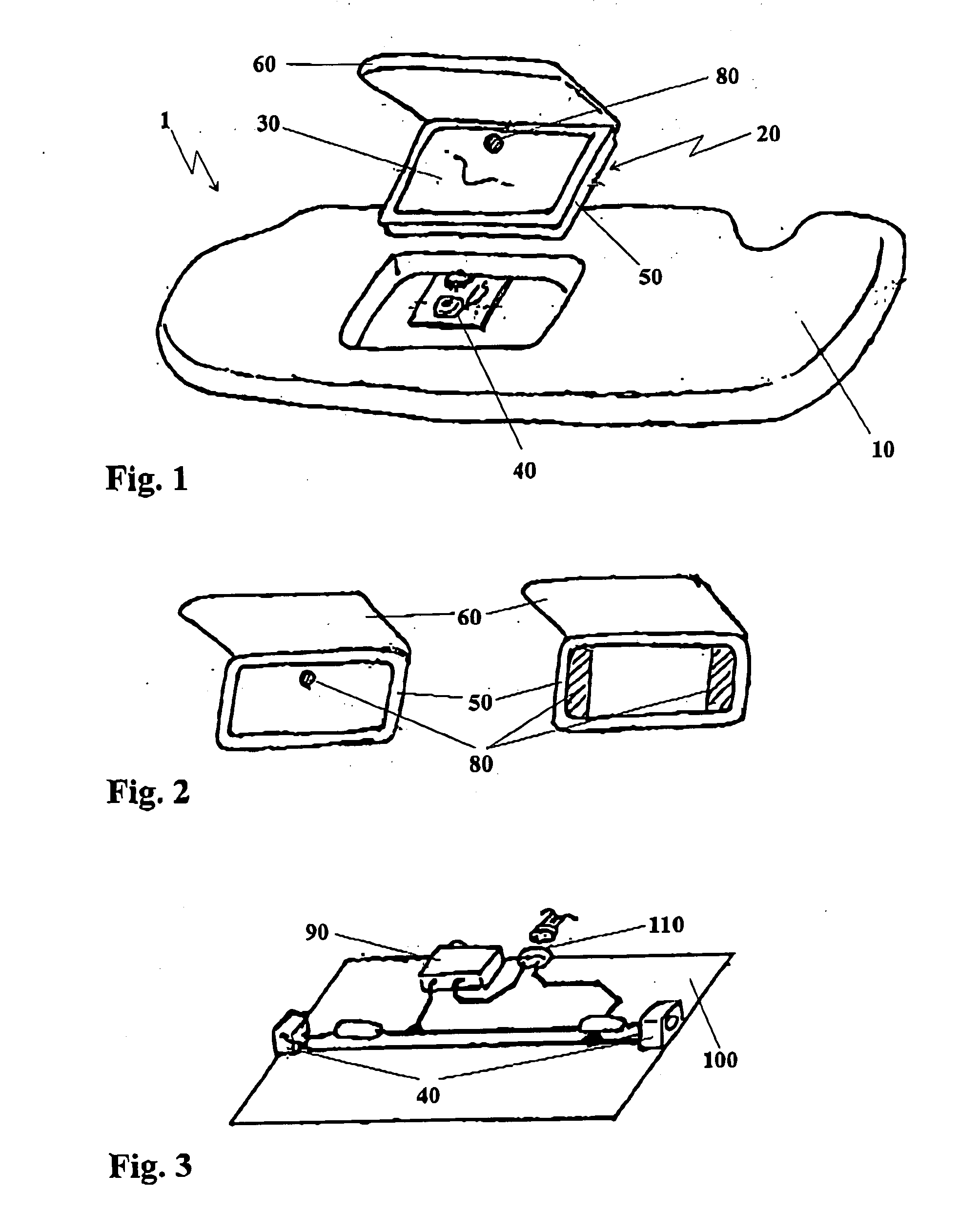
[0019] The mirrors mounted in the mirror unit are preferably covered by a moveable cover according to the invention. One cover for each of the mirrors can be provided in the case of a two-sided removable mirror unit i.e. in the case of a mirror unit with a mirror on the front and rear sides. The covers, which are hingably mounted on the mirror unit by means of a hinge or something similar, protect the mirrors and the mirror unit against mechanical damage as well as against soiling. Moreover, they add up to protecting the passengers against injuries caused by possible fragments of mirrors, if the mirrors of the mirror unit are destroyed in the case of an accident.
[0021] As already mentioned above, the at least two mirrors of the mirror unit are each covered by a moveable cover in a preferred embodiment of the present invention, Thus, the respective mirror can only be used if the cover has been opened and if the mirror has therefore been released. Correspondingly, it is merely necessary to illuminate that mirror whose cover has been opened. Therefore, the moveable cover is in accordance with the invention preferably provided with a switch, in order to switch the illumination of the uncovered mirror on if the cover is opened and in order to switch the illumination off again when the cover is subsequently closed. Based on this
assembly, the electrical
power consumption of the illuminated mirror unit can be reduced, thus increasing the service life of the respective power sources.
[0025] The illumination means are completely switched on in common mirror devices as soon as e.g. the cover of the mirror is opened. Switching on is independent of whether the light conditions in the surroundings require illumination or not. This results in an additional electrical power consumption which can be avoided. It is possible by means of electrical circuits to determine the brightness of the surroundings. A threshold value can be set in these circuits wherein the illumination means or merely a certain number of illumination means are switched on if the value is reached. It is also possible to operate the illumination means with reduced output. On this bases, the output of the illumination means of the mirror unit in accordance with the present invention is adapted to the light conditions of the surroundings. At the same time, a waste of power by not necessary illumination is reduced.
[0027] In order to configure the illuminated mirror unit with as little
spatial expansion as possible, the brightness-measuring circuit as well as said
printed circuit board with LED can be provided e.g. between the at least two mirrors or under said mirror. A corresponding sensor for determining the brightness of the surroundings is mounted behind a mirror. This is possible using an at least semi-transparent material which allows a good reflection for use as a mirror as well as the
transmittance of sufficient light for measuring behind the mirror to supply the sensor with light.

