Fault detection device

a fault detection and fault technology, applied in the field of fault detection devices, can solve the problems of long period, low accuracy, and serious damage, and achieve the effect of high accuracy in detecting network faults

Inactive Publication Date: 2006-08-17
FUJITSU LTD
View PDF26 Cites 74 Cited by
  • Summary
  • Abstract
  • Description
  • Claims
  • Application Information

AI Technical Summary

Benefits of technology

[0029] The present invention was created in view of the above circumstances, and an object thereof is to provide a fault detection device capable of high-accuracy detection of network faults by itself, without the need to interoperate with its associated device according to an identical protocol.

Problems solved by technology

If, in such carrier networks, a network fault occurs and recovery therefrom is delayed, serious damage is caused.
Redundant configuration is, however, meaningless unless a device itself can quickly detect faults with accuracy.
Where a silent fault (fault which does not trigger off automatic switchover to the redundant system or notification of an alarm to the operator and thus it is difficult to distinguish anomaly in operation) has occurred, the fault period lasts long, and in the case of an Ethernet network, looping is caused, possibly entailing congestion of frames.
This is because, if a looped path exists in the network, congestion of frames called broadcast storm is caused when a frame is broadcasted.
If this occurs, the broadcast frames instantly fill up the band, making normal communications unavailable.
. . , causing congestion.
However, even with the spanning tree formed as shown in FIG. 12, if the fault detection function fails to effectively work due to a silent fault occurring in the network 50, consistency of routing information among the nodes is lost, destroying the tree structure and possibly creating a loop.
Thus, since the service is disrupted for a long period of time, vendors have been making attempts to create their own vendor-specific protocols for detecting network faults.
However, existing network fault detection techniques based on vendor-specific protocols are subject to the precondition that the local device is aware of what the associated device monitors, as in the above example, and have the problem that the techniques can be applied only to the links connected by the devices of the same vendor's make within the network.
Thus, the existing techniques are not convenient enough in view of the fact that more and more carrier networks are configured in multi-vendor environments, and at present, standardization of network fault detection protocols is yet to be developed.

Method used


Image

  • Fault detection device
  • Fault detection device
  • Fault detection device

Examples


Embodiment Construction

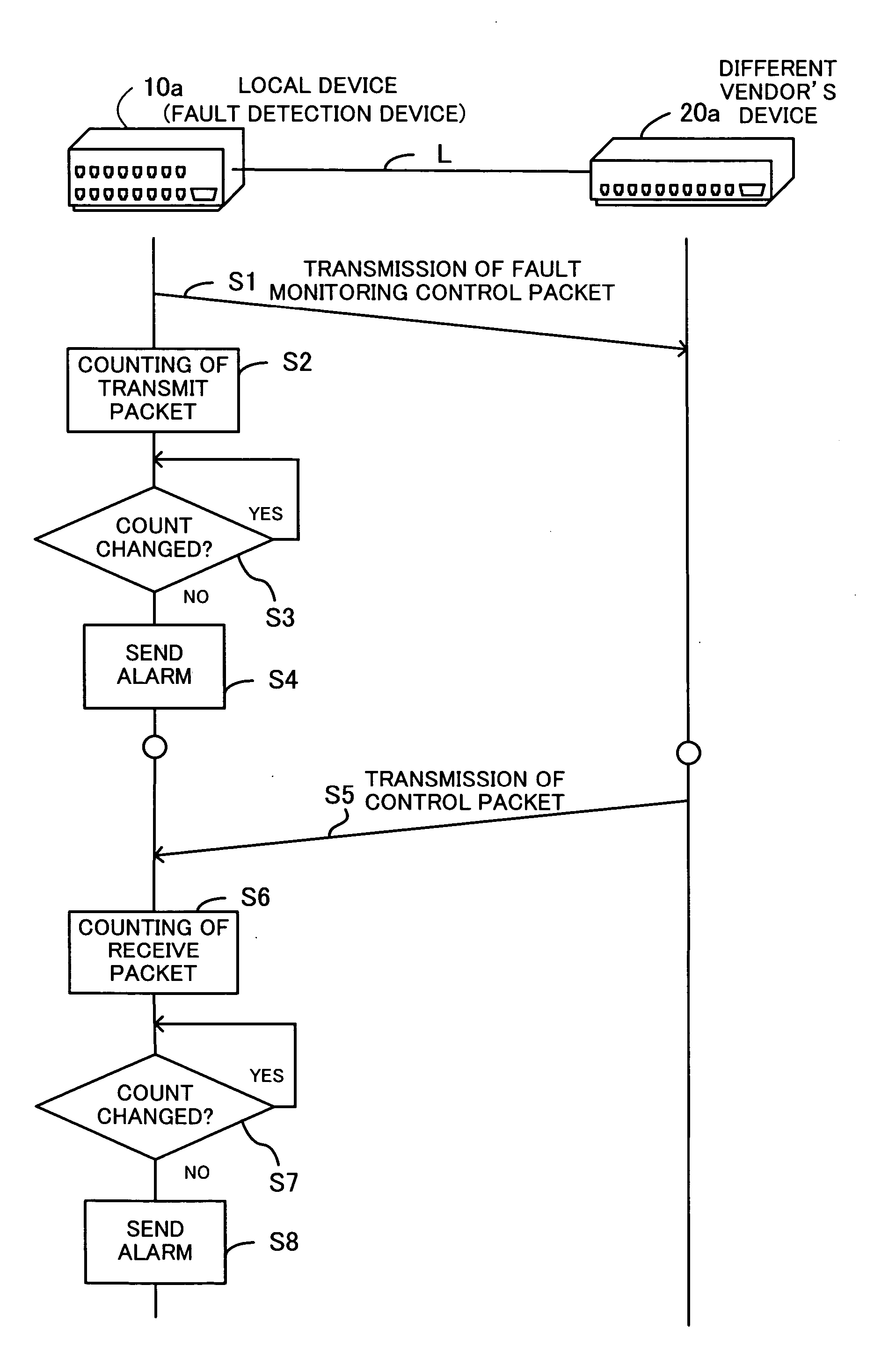
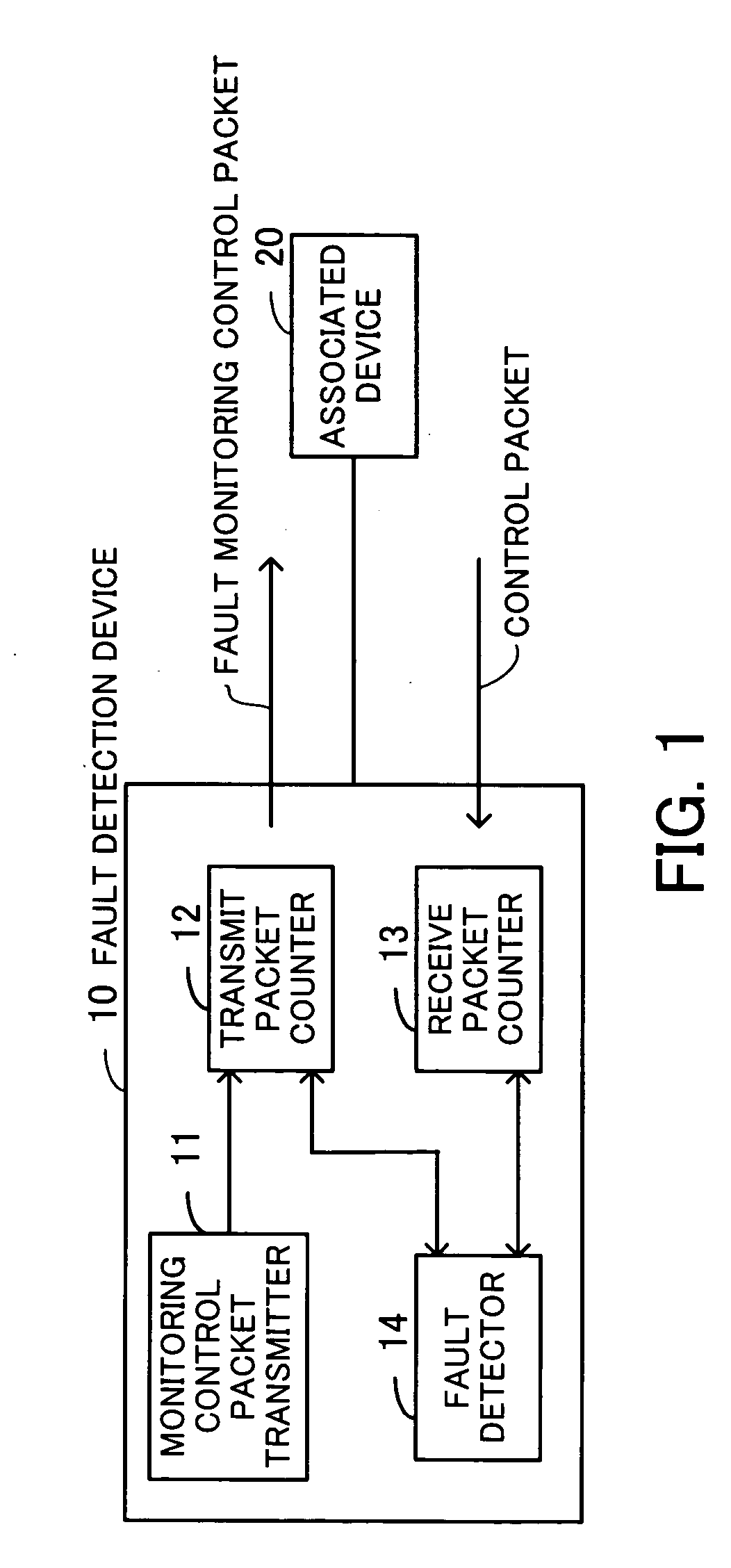
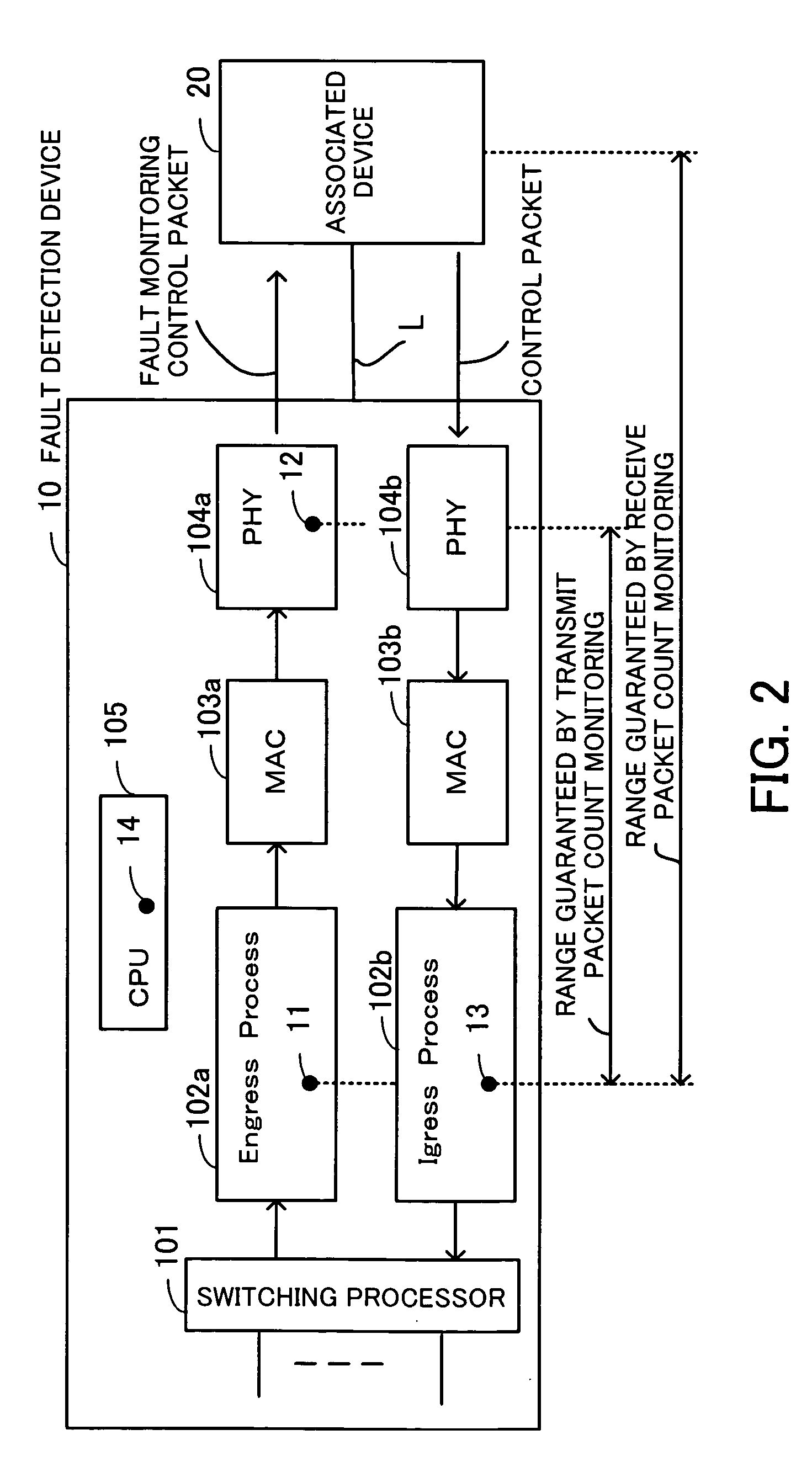
[0046] Preferred embodiments of the present invention will be described below with reference to the accompanying drawings. FIG. 1 illustrates the principle of a fault detection device. The fault detection device 10 comprises a monitoring control packet transmitter 11, a transmit packet counter 12, a receive packet counter 13 and a fault detector 14, and detects faults on a network. The function of the fault detection device 10 may be incorporated, for example, in a Layer 2 switch on a wide area Ethernet.

[0047] The monitoring control packet transmitter 11 generates a fault monitoring control packet and transmits the generated packet to an associated device 20 with which the fault detection device 10 need not interoperate to detect faults according to an identical protocol (i.e., to a device of a vendor's make different from that of the fault detection device). The transmit packet counter 12 keeps count of the transmitted fault monitoring control packet.

[0048] The receive packet cou...


PUM


Abstract

A fault detection device capable of detecting network faults by itself with high accuracy in multi-vendor environments, without the need to interoperate with an associated device according to an identical protocol. A monitoring control packet transmitter generates a fault monitoring control packet and transmits the generated packet to the associated device with which the fault detection device need not interoperate to detect faults according to the same protocol. A transmit packet counter keeps count of the transmitted fault monitoring control packet. A receive packet counter receives a control packet transmitted from the associated device, and keeps count of the received control packet. A fault detector monitors the count of transmitted packets and the count of received packets and, if at least one of the counts remains unchanged for a fixed period of time, judges that a fault has occurred and sends a fault notification to outside.

Description

CROSS-REFERENCE TO RELATED APPLICATIONS [0001] This application is based upon and claims the benefits of priority from the prior Japanese Patent Application No. 2005-039528, filed on Feb. 16, 2005, the entire contents of which are incorporated herein by reference. BACKGROUND OF THE INVENTION [0002] 1. Field of the Invention [0003] The present invention relates to fault detection devices, and more particularly, to a fault detection device for detecting faults on a network. [0004] 2. Description of the Related Art [0005] In recent years, telecommunications carriers provide wide area Ethernet (“Ethernet” is a registered trademark) as one of carrier services using LANs (Local Area Networks) and the service is more and more diffusing. Wide area Ethernet is a service whereby a plurality of Ethernet LAN environments are interconnected by Layer 2 switches to be integrated into a single network. [0006] Wide area Ethernet does not require an expensive router (Layer 3 switch) but uses an inexp...

Claims


Application Information

Patent Timeline
Patent Type & Authority Applications(United States)
IPC IPC(8): H04L12/26G06F11/00H04J3/14G01R31/08G08C15/00H04J1/16H04L1/00H04L69/40
CPCH04L1/24H04L41/06H04L43/10
Inventor SASAGAWA, YASUSHIKAWARAI, KENICHIDOUKAI, MASAMITAKATORI, KOU
Owner FUJITSU LTD
Why Eureka
Try Eureka