Pressure activated safety valve with improved flow characteristics and durability

a technology of flow characteristics and durability, applied in the direction of catheters, suction devices, other medical devices, etc., can solve the problems of small amounts of blood oozing into the proximal end of the catheter, the catheter is not easy to insert and remove, and the catheter is difficult to clean

Active Publication Date: 2006-08-17
ANGIODYNAMICS INC
View PDF99 Cites 74 Cited by
  • Summary
  • Abstract
  • Description
  • Claims
  • Application Information

AI Technical Summary

Problems solved by technology

It is impractical and dangerous to insert and remove the catheter for each dialysis session.
However, even small amounts of blood oozing into the proximal end of the catheter may be dangerous, as thrombi can form therein due to coagulation.
This method is often unsatisfactory because the repeated application of the clamp may weaken the walls of the catheter due to the stress placed on the walls at a single point.
In addition, the pinched area of the catheter may not be completely sealed allowing air to enter the catheter which may coagulate any blood present within the catheter.
However, the unreliability of conventional valves has rendered them unsatisfactory for extended use.
The effect of the presence of valves within the flow of blood may cause some potentially harmful effects.
If the decrease in pressure is sufficiently large, the pressure may fall below the vapor pressure of the fluid, causing the formation of gas bubbles.
The formation of bubbles, or cavitation, in blood flowing through the vascular system may be dangerous to the patient, because the gas bubbles may become trapped in a blood vessel and may impede flow of blood therethrough.
Flow recirculation within the valve also may cause deposits of biological material to form in the passages, which also may leave the valve and become lodged in a blood vessel, impeding passage of blood.
The recirculation within the valve may also cause damage to the blood cells which pass through the valve.

Method used


Image

  • Pressure activated safety valve with improved flow characteristics and durability
  • Pressure activated safety valve with improved flow characteristics and durability
  • Pressure activated safety valve with improved flow characteristics and durability

Examples


Embodiment Construction

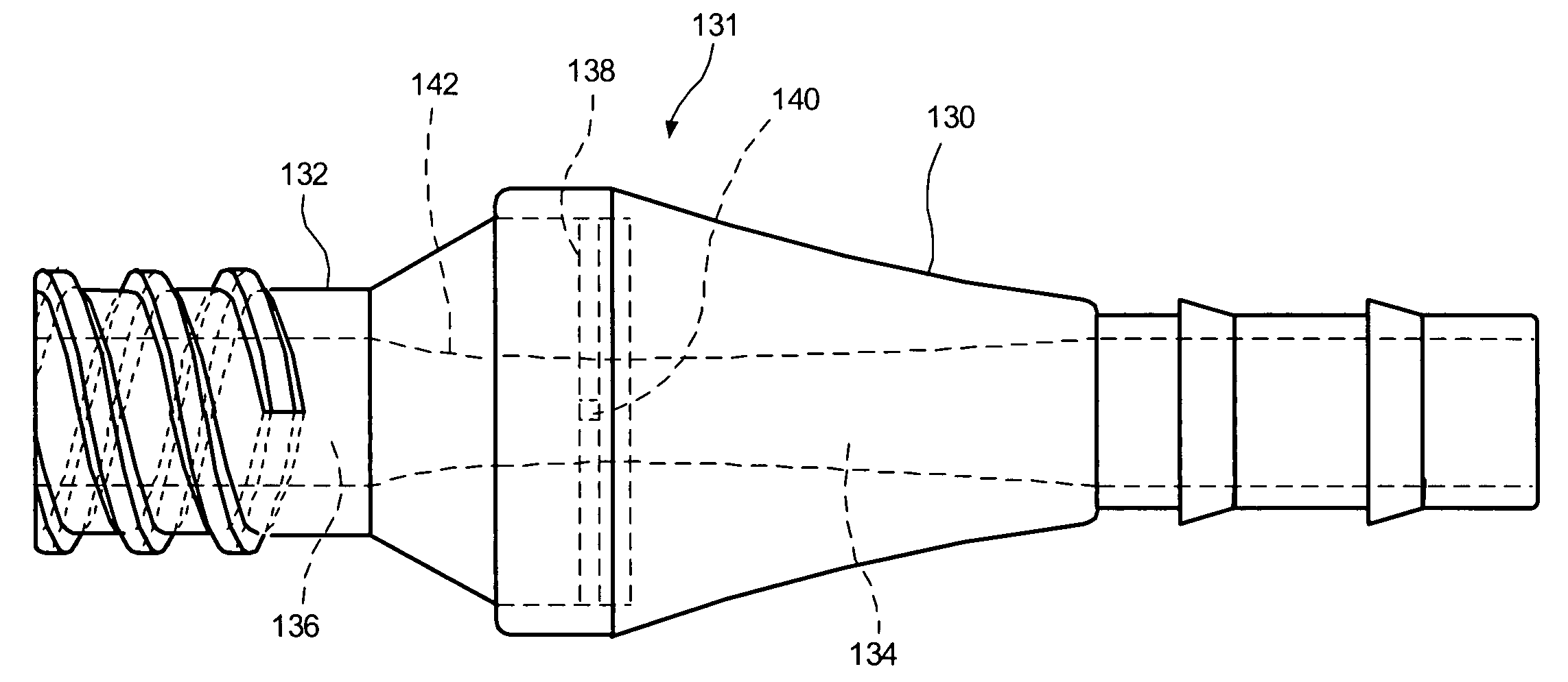
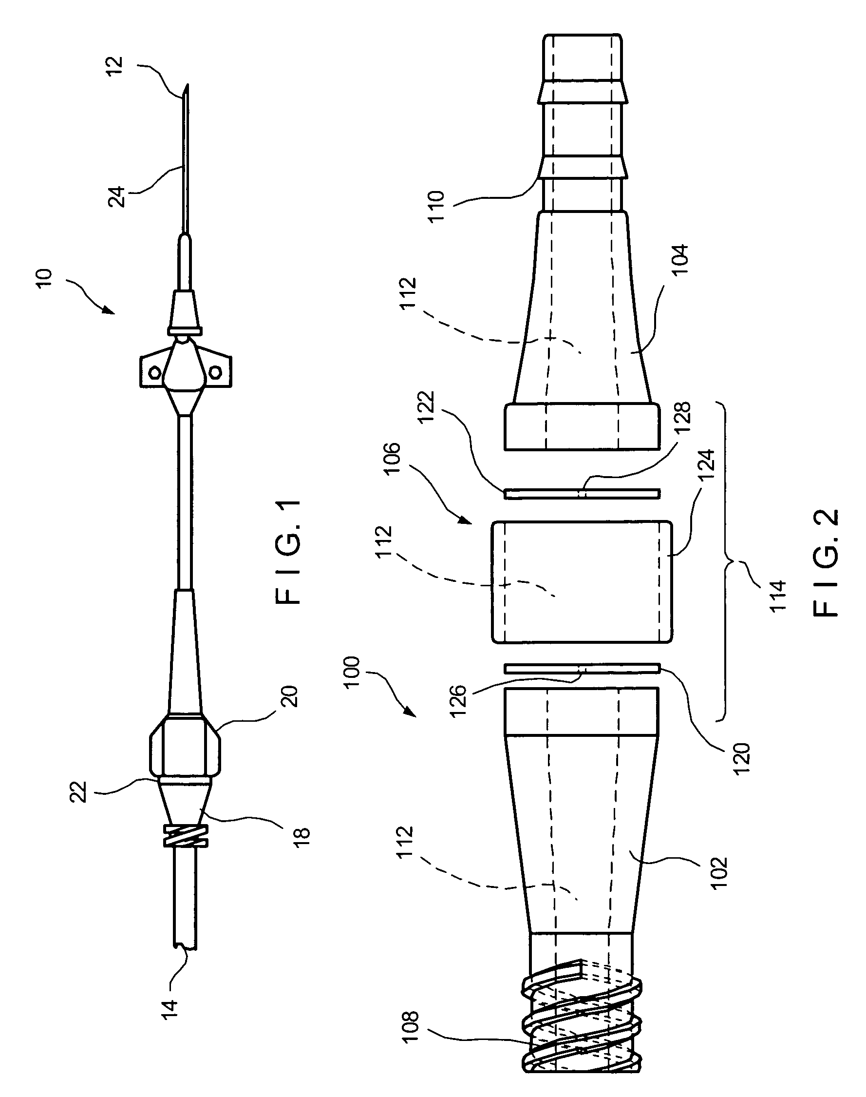
[0020] The present invention may be further understood with reference to the following description and the appended drawings, wherein like elements are referred to with the same reference numerals. The present invention is related to medical devices that are used to access the vascular system of a patient, and in particular to pressure activated safety valves used in kidney dialysis catheters. It will be apparent to those of skill in the art that the present invention may be adapted for use in other medical access devices.

[0021] Semi-permanently placed catheters may be useful for a variety of medical procedures which require repeated access to a patient's vascular system in addition to the dialysis treatments mentioned above. For example, kidney dialysis may be repeated on a regular basis for extended periods of time. For safety reasons, as well as to improve the comfort of the patient, access to the patient's vascular system may be better carried out with an implantable, semi-perm...


PUM


Abstract

A valve assembly for vascular access, comprising a body defining a lumen adapted for flowing blood, the body including a luer housing for connection with a first blood conduit and a barb housing for connection with a second blood conduit and a plurality of slitted membranes disposed within the body portion, each of the slitted membranes generating a partial pressure drop for flow therethrough, each of the partial pressure drops being smaller than a total pressure drop for flow through the body portion.

Description

[0001] The present application incorporates by reference the entire disclosures of the U.S. Applications entitled [insert as filed titles, names of inventors and filing dates of 10123-00701, 00801, 00901, 01001, and 03701]BACKGROUND OF THE INVENTION [0002] Many medical procedures require repeated and prolonged access to a patient's vascular system. For example, during dialysis treatment blood may be removed from the body for external filtering and purification, to make up for the inability of the patient's kidneys to carry out that function. In this process, the patient's venous blood is extracted, processed in a dialysis machine and returned to the patient. The dialysis machine purifies the blood by diffusing harmful compounds through membranes, and may add to the blood therapeutic agents, nutrients etc., as required before returning it to the patient's body. Typically the blood is extracted from a source vein (e.g., the vena cava) through a catheter sutured to the skin with a dist...

Claims


Application Information

Patent Timeline
Patent Type & Authority Applications(United States)
IPC IPC(8): A61M5/00
CPCA61M1/367A61M39/0613A61M39/26A61M1/3661
Inventor QUIGLEY, KARLA WEAVERDICARLO, PAULWOLFSON, MARK
Owner ANGIODYNAMICS INC
Why Eureka
Try Eureka