Embolic protection device

a protection device and emboli technology, applied in the field of emboli capturing devices, can solve the problems of emboli being undetected in the blood flow of the vasculature, blood clots and thromboses being released into the blood flow, and many potential sources of undesirable emboli

Inactive Publication Date: 2006-08-17
COOK INC
View PDF99 Cites 101 Cited by
  • Summary
  • Abstract
  • Description
  • Claims
  • Application Information

AI Technical Summary

Benefits of technology

[0010] Most preferably, the catheter is a balloon catheter for treating a stenotic lesion, and the hub and bristles provide distal protection for the balloon catheter. T

Problems solved by technology

There are many potential sources of undesirable emboli.
During the stenosis procedure however, there is a r

Method used


Image

  • Embolic protection device
  • Embolic protection device
  • Embolic protection device

Examples


Embodiment Construction

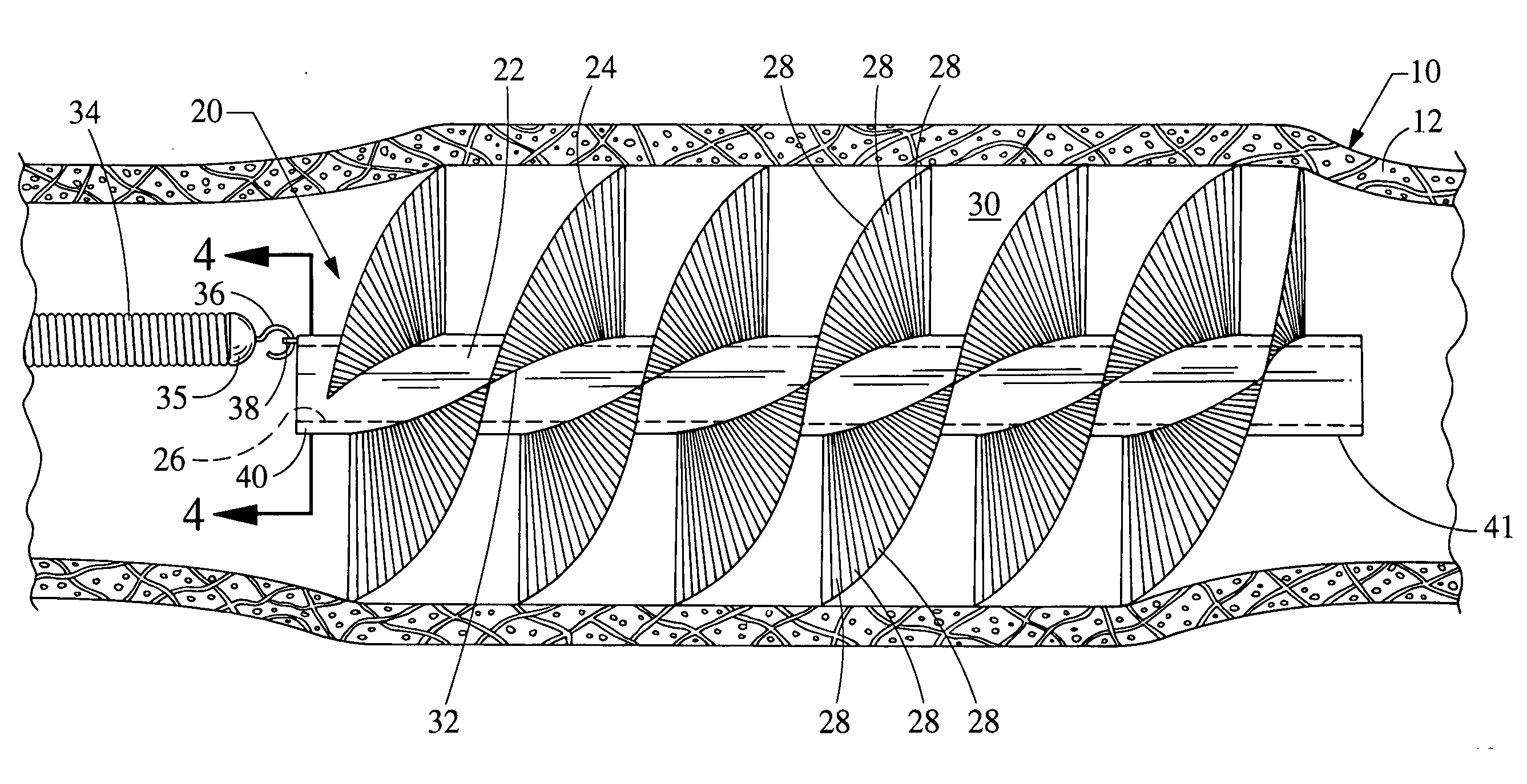
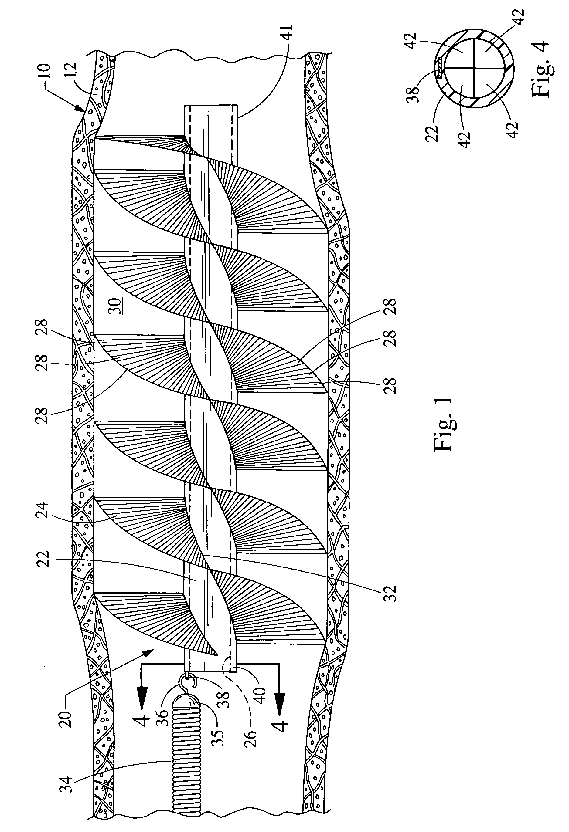
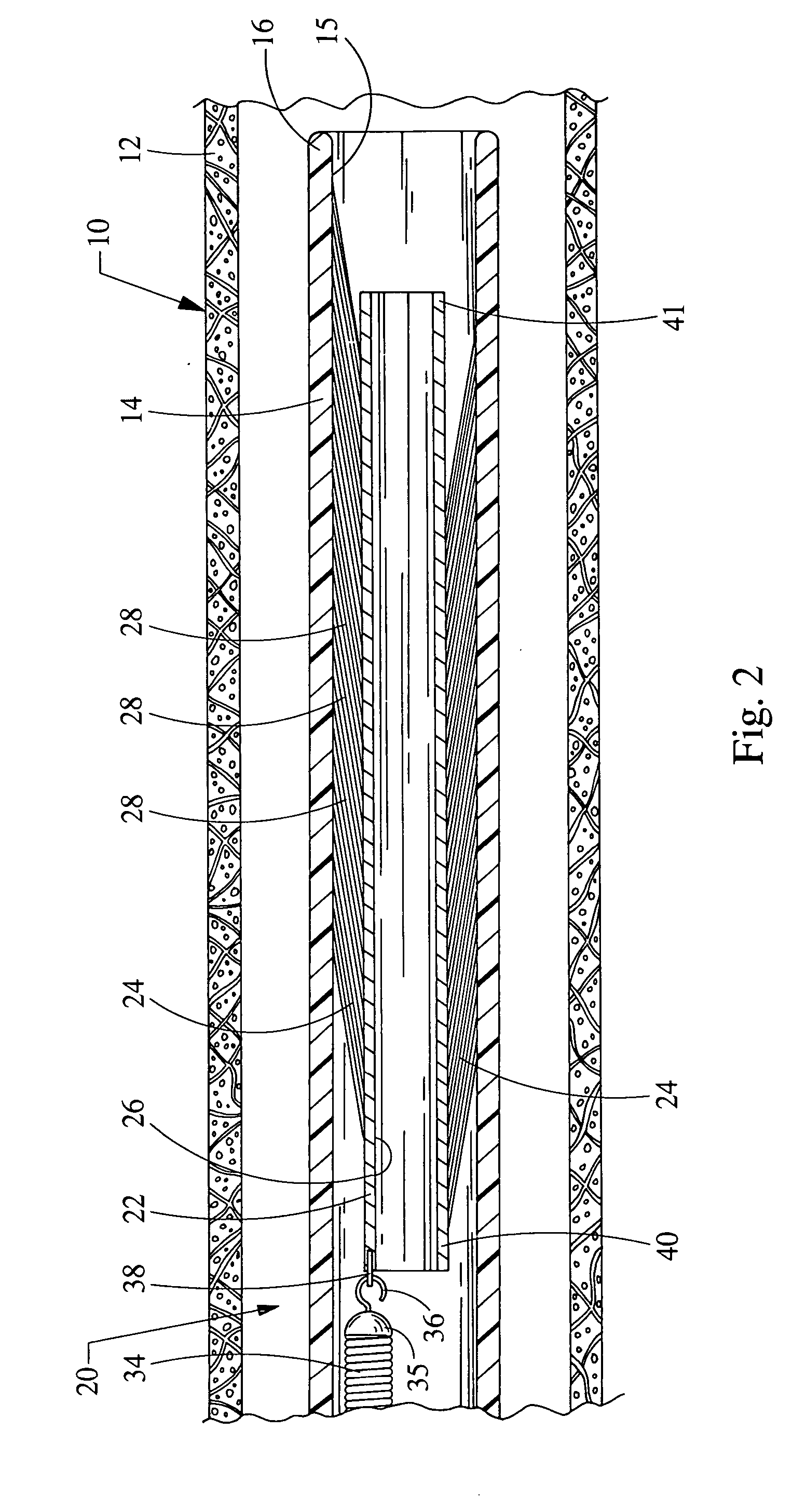
[0019] Turning now to the figures, FIG. 1 depicts a cross-sectional view of the embolic protection device 20 constructed in accordance with the teachings of the present invention. The device 20 is designed to be positioned inside a body lumen 10 which has a bodily fluid passing therethrough, such as a blood vessel. The bodily vessel 10 is defined by a vessel wall 12. The embolic protection device 20 generally comprises an elongated hub 22 and at least one projection 24 extending radially from the hub. As shown in the figures, the at least one projection 24 may comprise a plurality of bristles 28 which are attached to the outer periphery of the hub 22. The bristles are preferably constructed of a biocompatible plastic such as polyamide, polytetrafluroethylene (PPFE), polyethylene (LDPE, HDPE) or polyvinylchloride (PVC), although may be constructed of other known materials such as metals (e.g. nitinol (Ni-Ti superelastic alloy) or other alloys) other plastics, elastomers, or composite...


PUM


Abstract

An embolic protection device generally includes an elongated hub and at least one projection. The projection defines a tortuous pathway between the hub and the vessel wall to prevent emboli from following the pathway and passing beyond the device. The tortuous pathway is structured to permit the bodily fluid to follow the pathway and pass beyond the device.

Description

CROSS-REFERENCE TO RELATED APPLICATION [0001] This application claims the benefit of U.S. Provisional Application Ser. No. 60 / 652,956, filed on Feb. 15, 2005, entitled “EMBOLIC PROTECTION DEVICE,” the entire contents of which are incorporated herein by reference.FIELD OF THE INVENTION [0002] The present invention relates to medical devices. More particularly, the present invention relates to emboli capturing devices and methods for capturing emboli within a body lumen. BACKGROUND OF THE INVENTION [0003] Embolic protection devices are percutaneously placed in a body lumen to prevent emboli from traveling and creating an undesirable embolism, e.g., pulmonary embolism. For example, vena cava filters are being used for trapping emboli in the vena cava to prevent pulmonary embolism. There are many potential sources of undesirable emboli. [0004] For Example, treatments for a stenotic lesion provide a potential in releasing blood clots and other thrombi plaque in the vasculature of the pat...

Claims


Application Information

Patent Timeline
IPC IPC(8): A61M29/00
CPCA61F2230/0069A61F2230/0091A61F2230/0095A61F2/013A61F2002/068A61F2002/018A61F2230/0006
Inventor PAL, DHARMENDRAOSBORNE, THOMAS A.PAUL, RAM H. JR.
Owner COOK INC
Why Eureka
Try Eureka