
Fiber based embolism protection device

a protection device and fiber technology, applied in the field of fiber based embolism protection devices, can solve the problems of localized cell death or microinfarct, stroke leading to confusion, paralysis, paralysis, etc., and achieve meaningful long-term clinical benefits, prevent ischemic complications, and reduce platelet aggregation

Active Publication Date: 2008-05-08
MEDTRONIC INC
View PDF86 Cites 84 Cited by
  • Summary
  • Abstract
  • Description
  • Claims
  • Application Information

AI Technical Summary

Benefits of technology

The invention is about a device and method for protecting against embolisms, which are blood clots that can cause serious health problems. The device consists of a fiber support structure connected to a guidewire, with biocompatible fibers that can be expanded or contracted to fit different vessel diameters. The device can be placed within a patient's vessel to catch any emboli that might occur during a medical procedure. The invention can help prevent the need for blood clot removal procedures, which can be risky and uncomfortable for patients.

Problems solved by technology

Loss of blood flow to surrounding tissue causes localized cell death or microinfarcts.
Cerebral microinfarcts can cause stroke leading to confusion, disturbance of speech, paralysis, visual disturbances, balance disturbances and even death (5).
In the heart, emboli can cause myocardial infarcts, i.e. heart attacks.
Anything which loosens or breaks up this plaque can generate emboli.
The clinical ramifications of emboli are staggering.
Ironically, the surgical interventions used to remove or bypass the plaque of arteriosclerosis (e.g., balloon dilatation angioplasty, endarterectomy, bypass grafting and stenting) can themselves disrupt plaque.
But CABG is not the only procedure with potential to generate emboli.
While daunting, this figure fails to include the social and financial burden placed on family members upon hospital release.
In summary, embolic events complicating percutanuous endovascular procedures cause high rates of clinically observed neurological disturbances and cardiovascular disease, decreased quality of life and increased patient care spending.
Glyoprotein IIb / IIIa inhibitors have been used for percutaneous coronary interventions to reduce platelet aggregation, but also fail to show meaningful long term clinical benefit.
Lack of benefit may be attributed to the way in which these emboli are generated.
In most cases embolization develops from physical disruption of fibrotic plaque.
This is a significant clinical problem.
These complications are due in large measure to CPB-generated emboli.
Cerebral microinfarctions can cause confusion, disturbances of speech, paralysis, visual disturbances, balance disturbances and other neurological deviations.
As a result, blood flow to the distal vascular bed can be diminished and periprocedural end-organ ischemia and infarction can result.
Distal embolization of large particles produced at the time of such interventions as balloon inflation or stent deployment may obstruct large, epicardial vessels, and smaller particles (as small as 15-100 microns) can cause microinfarcts and / or myocardial infarctions and left ventricular dysfunction.
Blockage of capillaries associated with the coronary arteries can result in corresponding microinfarctions / microinfarcs.
Surgical procedures for the treatment of renal artery stenosis can also generate emboli.
Foreign material in the stream of flow can cause turbulence or low flow.
Such flow conditions have been shown to increase rates of infection.
Thrombus not only generates emboli, but also increases the risk of infection.
It is evident that a wide variety of embolic events cause high rates of clinically observed symptoms, decreased quality of life and increased patient care spending.

Method used


Image

  • Fiber based embolism protection device
  • Fiber based embolism protection device
  • Fiber based embolism protection device

Examples


example 1

SCF Fibers Biological Agent Absorption and Delivery

a. Loading the Fiber

[0192] This example demonstrates the capacity of SCF fibers to deliver higher quantities of biologically agent than round fibers. In this experiment, bovine serum albumin (albumin) was used. Albumin, a biological serum protein, was chosen because it has a similar molecular weight to that of TPA.

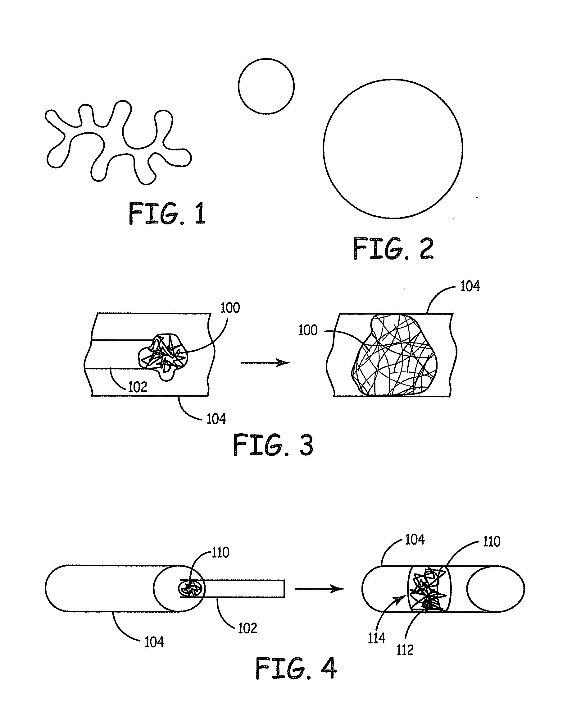
[0193] Two different cross-sectional geometries were evaluated. Group # 1 consisted of standard round fibers and group #2 insisted of the SCF fibers (specifically 4DGT™ fibers, Fiber Innovation Technology, Inc. Johnson City Tenn.). The cross sections of the fibers are shown schematically in FIGS. 1 and 2. Both fiber were six denier polyester fibers with similar surface finishes. Six-fiber bundles (3 from each group) of approximately the same size were weighted. (See Table 1.) Samples were labeled and placed in 15 ml polymer BD Falcon® centrifuge tube. A 5 ml quantity of (4 mg per ml albumin solution prepared from Bovin...

example 2

Solution Tracking Along the Fibers Grooves

[0198] The following example demonstrates the feasibility of applying a biological agent, which will track along the grooves in the fiber to provide greater agent availability within the device. This experiment will demonstrate that a round fiber did not provide similar increased agent availability. Two different cross-sectional fiber geometries were evaluated. Group # 1 fibers were standard round fibers, and group #2 fibers was the SCF fibers (specifically 4DG™ fibers, Fiber Innovation Technology, Inc. Johnson City Tenn.). Both fiber types were six denier polyester fibers with similar surface finishes. Two bundles of fibers were aligned. The fibers were bound at both ends and then compressed slightly to formulate a bulb like appearance. One end of the fibers was then attached to a syringe, which contained Coomassie Blue (CB) (Coomassie Brilliant Blue Bio-Rad Labratories, Hercules, Calif. 94547 in distilled water). The dye was injected into...

example 3

Evaluation with an In Vitro Flow Loop

[0200] This example demonstrates the utility of an in vitro flow loop for evaluation of an embolism protection device as well as provides an evaluation of two embodiments of an embolism protection device, one with incorporated tPA and one without incorporated tPA.

[0201] The interrupted flow loop was developed to mimic the environment of a native coronary artery. The apparatus consisted of four components: a circulation unit, the embolism protection device, the blood / media, and the emboli. The flow loop was constructed as indicated in FIG. 42. The circulation unit had a heated reservoir 500 holding blood and media 502, tubing 504, a pump 506, injection ports 503, 510 and a collection vessel 512. Embolism protection device 514 was held in a fixture 516 within tubing 504. Flow through the system is noted in FIG. 42 with four flow arrows.

[0202] Embolism protection device 514 was formed with two sections of structure. The layered system for purpose...


PUM


Abstract

Improved embolism protection devices comprises fibers that can have one configuration for delivery of the device and a second configuration in which the device is deployed for filtering of flow within a vessel. In some embodiments, the fibers can be connected to a fiber support, which is connected to an actuating element. The actuating element controls the transition from the delivery configuration to the deployed configuration. The embolism protection device can comprise a guidewire. The fibers can be attached at one end to a fiber support structure and at another end to the guidewire. A hypotube can be attached to the proximal end of the fibers while the guidewire is attached at the distal end of the fibers with the guidewire extending within a central channel of the hypotube. The hypotube can be used to guide the delivery of treatment structures, such as a balloon and / or a stent.

Description

CROSS REFERENCE TO RELATED APPLICATIONS [0001] This application claims priority to copending U.S. patent application Ser. No. 10 / 795,131, filed Mar. 6, 2004, which claims benefit to provisional patent application Ser. No. 60 / 489,044, filed Jul. 22, 2003 to Ogle et al., entitled “Embolism Protection System,” both of which are incorporated herein by reference.FIELD OF THE INVENTION [0002] The invention relates to a device and corresponding systems for preventing blockage of flow of blood or other bodily fluids to distal organs or other distal vessels. In particular, the invention relates to devices suitable for placement within a vessel, such as a blood vessel to trap occlusions, such as emboli, for their dissolution or removal, as well as related methods. BACKGROUND OF THE INVENTION [0003] An embolus can be any particle comprising a foreign or native material, which enters the vascular system or other vessel of the body with potential to cause occlusion of blood flow. Emboli can be f...

Claims


Application Information

Patent Timeline
Patent Type & Authority Applications(United States)
IPC IPC(8): A61F2/02A61BA61M25/09A61M25/12A61M29/00G02B6/00
CPCA61F2/01A61M25/09A61M2025/09175A61F2230/0006A61F2230/005B33Y80/00
Inventor GALDONIK, JASONOGLE, MATTHEWPOKORNEY, JIMHINNENKAMP, THOMAS
Owner MEDTRONIC INC
Learn More