Embolic protection device and methods of use

a protection device and a technology of a protective device, applied in the field of embolism protection devices and methods of use, can solve the problems of blockages, whether partial or full, that can have serious medical consequences, damage to the heart, and other vessels are also prone to narrowing

Active Publication Date: 2012-07-17
ST JUDE MEDICAL CARDILOGY DIV INC
View PDF260 Cites 84 Cited by
  • Summary
  • Abstract
  • Description
  • Claims
  • Application Information

AI Technical Summary

Benefits of technology

[0012]In an alternate embodiment, the first elongate tubular member may further be surrounded by a kink resistant structure, for example a kink resistant braid or a kink resistant coil. The kink resistant coil may be comprised of a ribbon wire and may have further be secured at the proximal and distal ends of the coil to prevent uncoiling by one or more laser welds joining one or more adjacent turns of the coil. In such an embodiment, the second elongate tubular member may then be secured to the first elongate member by mounting the second elongate tubular member to the kink resistant structure.
[0021]According to another aspect of the invention, a method for treating a diseased blood vessel is provided. The method includes advancing an elongate tubular member into the blood vessel through the lumen of the guide catheter, positioning the elongate tubular member within the diseased blood vessel, inflating the expandable sealing member located on the distal end of the of the elongate tubular member to form a seal between the region of interest of the diseased blood vessel and the distal end of the guide catheter; and applying a vacuum to the elongate tubular member to cause retrograde blood flow in the blood vessel and to carry fluid into the lumen of the elongate tubular member.
[0023]According to another aspect of the invention, a method for treating a diseased blood vessel is provided. The method includes advancing a guide catheter proximal to the blood vessel, advancing an elongate tubular member into the blood vessel through the lumen of the guide catheter and beyond the distal opening, wherein the proximal end of the elongate tubular member extends proximally outside the patient during use, positioning the elongate tubular member within the diseased blood vessel, inflating the expandable sealing member located on the distal end of the of the elongate tubular member to occlude normal ante grade blood flow in the blood vessel proximal to the region of interest, and applying a vacuum to the elongate tubular member to cause retrograde blood flow in the blood vessel and to carry fluid into the lumen of the elongate tubular member.

Problems solved by technology

Such blockages, whether partial or full, can have serious medical consequences, depending upon their location within a patient's vascular system.
Narrowing or blockage of the coronary vessels that supply blood to the heart, a condition known as atherosclerosis, may cause damage to the heart.
Other vessels are also prone to narrowing, including carotids, renals, cerebrals, and other peripheral arteries.
The saphenous vein graft (SVG), however, is also susceptible to becoming occluded in a manner similar to that of the bypassed vessel.
Each of the above described procedures carries with it the risk that some of the treated plaque, or other obstructive material such as thrombus, will be disrupted, resulting in embolic particulates released in the bloodstream.
These emboli, if allowed to flow through the vascular system, may cause subsequent infarctions or ischemia in the patient.
SVGs treated by angioplasty or atherectomy carry a particularly high risk of this result, but such problems are also encountered in the other types of procedures mentioned, such as carotids, or native coronary arteries, particularly those whose lesions include thrombus, such as those associated with acute myocardial infarction (AMI).
While this system has shown a decrease in emboli related complications in patients undergoing such treatments, the event rate remains significant.
One particular problem with this system is passing the guidewire and balloon through the narrowed or occluded area prior to occlusion with the balloon, creating the risk that emboli will be produced as the balloon passes through the blockage.
Thus, any particulate or plaque disturbed during this passage which forms emboli prior to inflation of the balloon is free to flow through the vascular system, increasing the risk for infarction or ischemia.
Also, any debris or embolic particulate matter which gathers around the edges of the balloon may slip downstream during deflation and retrieval of the balloon.
In addition, this system requires that blood flow be totally occluded in the vessel for relatively prolonged intervals that may induce adverse cardiac events.
Although this may not be a problem clinically, many patients perceive the occlusion of blood flow for this period of time as problematic.
However, because the filter must pass through the blockage, it suffers from the same drawback as the previous system—risk of the creation of emboli during passage of the filter through the blockage.
In addition, it is difficult to deploy the filter securely against the walls of the vessel to prevent flow around the filter and any debris or particulate matter which gathers around the edges of the filter may slip downstream during its retrieval.
The filter also cannot prevent the passage of certain neurohumoral or vasoactive substances which are released into the blood during the procedure and may contribute to generalized vasospasm of the distal coronary tree.

Method used


Image

  • Embolic protection device and methods of use
  • Embolic protection device and methods of use
  • Embolic protection device and methods of use

Examples


Embodiment Construction

[0048]The present invention provides a system and method for evacuating emboli, particulate matter and other debris from a blood vessel, and particularly from an occluded blood vessel. As used herein, an “occlusion,”“blockage,” or “stenosis” refers to both complete and partial blockages of the vessels, stenoses, emboli, thrombi, plaque, debris and any other particulate matter which at least partially occludes the lumen of the blood vessel.

[0049]This method and apparatus are particularly suited to be used in diseased blood vessels that have particularly fragile lesions, or vessels whereby the consequences of even small numbers of small emboli may be clinically significant. Such blood vessels include diseased SVGs, carotid arteries, coronary arteries with thrombus such as associated with AMI, and renal arteries. However, it is contemplated that the method and apparatus may also be applied to peripheral, neuro, and other vascular and non-vascular applications.

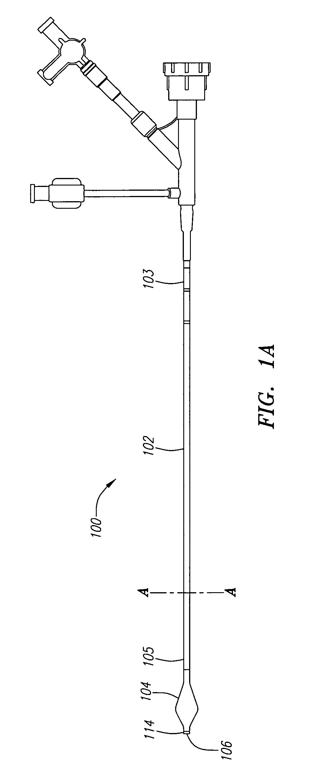
[0050]FIG. 1A illustrates ...


PUM


Abstract

An evacuation sheath assembly and method of reducing or removing a blockage within a vessel without permitting embolization of particulate matter is provided. The evacuation sheath assembly includes a first elongate tubular member, having proximal and distal ends and a main lumen configured to be placed in fluid communication with a blood vessel. An expandable member is provided on a distal portion of the tubular member and is configured to form a seal with the blood vessel. The evacuation assembly further includes a second elongate tubular member having proximal and distal ends and an inflation lumen configured to be placed in fluid communication with the expandable member and a gas inflator. The gas inflator includes a high pressure gas source and a mechanism for regulating the pressure of the gas delivered by the gas inflator. The gas inflator is configured to be placed in fluid communication with the proximal end of the inflation lumen in order to provide a regulated pressure gas source for inflating the expandable member. A method of treatment of a blood vessel using the evacuation sheath assembly includes advancing the evacuation sheath assembly into the blood vessel through a guide catheter. The expandable member is inflated to provide form a seal between the blood vessel and the guide catheter and a vacuum is applied to the main lumen of the first elongate tubular member to cause retrograde blood flow and carry fluid into the main lumen of the evacuation sheath assembly.

Description

FIELD OF THE INVENTION[0001]The present invention relates to apparatus and methods used to prevent the introduction of emboli into the bloodstream during and after surgery performed to reduce or remove blockage in blood vessels.BACKGROUND OF THE INVENTION[0002]Narrowing or occlusion of blood vessels, such as the walls of an artery, inhibits normal blood flow. Such blockages, whether partial or full, can have serious medical consequences, depending upon their location within a patient's vascular system. Narrowing or blockage of the coronary vessels that supply blood to the heart, a condition known as atherosclerosis, may cause damage to the heart. Heart attacks (myocardial infarction) may also result from this condition. Other vessels are also prone to narrowing, including carotids, renals, cerebrals, and other peripheral arteries.[0003]Various surgical procedures are currently used to reduce or remove the blockage in blood vessels. Such procedures include balloon angioplasty, which ...

Claims


Application Information

Patent Timeline
Patent Type & Authority Patents(United States)
IPC IPC(8): A61M29/00A61F2/958
CPCA61M25/1018A61B17/22032A61M25/005A61M2025/0034A61M2025/0037A61M2205/8225A61M25/10181
Inventor HACKETT, STEVEN S.STAINBROOK, ERIC S.JANECEK, THOMAS F.TREMBATH, CHAD W.DUSBABEK, ANDREW J.DRONTLE, JOHN R.PHILLIPS, JOEL D.RESSEMANN, THOMAS V.THUNSTROM, KYLE L.KEITH, PETER T.
Owner ST JUDE MEDICAL CARDILOGY DIV INC
Why Eureka
Try Eureka