Delayed memory device

a memory device and delay technology, applied in the field of medical devices, can solve the problems of unsatisfactory reduction of the circumference of the mitral annulus, risk of device dislocation,

Inactive Publication Date: 2006-08-17
EDWARDS LIFESCIENCES AG
View PDF82 Cites 34 Cited by
  • Summary
  • Abstract
  • Description
  • Claims
  • Application Information

AI Technical Summary

Benefits of technology

[0018] According to another aspect of the present invention, a medical device for providing a change of shape in a part of the body of an organism comprises a first set of forces working towards a change of shape of the device, and a second set of forces working for preserving a present shape of the device and thereby counteracting said first set of forces. Said first and said second sets of forces are each inherent in a solid material of the device, and the forces of said second set of forces are arranged to decrease as a result of said solid material interacting chemically with said part of the body. As a result of the chemical interaction between the solid material of the device and the surrounding body, the forces of the second set of forces decrease and thus allow the device to provide said change of shape after a while, when parts of the device have become fixed in the body by a healing process. An advantage of the present invention, except that it provides a more secure fixation, is that there is no need for a stabilizing surgical instrument for keeping a present shape of the device during operation, since the shape is preserved by means of said second set of forces being inherent in the device itself.
[0019] Preferably said second set of forces is inherent in a decomposable material as mentioned above.
[0020] Said forces of said second set of forces are preferably arranged to decrease as a result of said solid material being decomposed by said part of the body.
[0021] In a preferred embodiment of the invention, said second set of forces is inherent in a resorbable material as described above.
[0022] Preferably, said forces of said second set of forces are arranged to decrease as a result of said solid material being resorbed by said part of the body.
[0023] In another preferred embodiment, said first set of forces is inherent in an elastic material.

Problems solved by technology

However, the position fixation of the elongate stent in the coronary sinus by means of the hooks might be insufficient, so that the sudden release of the contraction of the elongate stent dislocates it.
This dislocation of the device might result in unsatisfactory reduction of the circumference of the mitral annulus.
Also with this method there is a risk of dislocation of the device, since the surgeon might accidentally move insufficiently fixed stent sections out of their proper position while manipulating them from outside the vein system.

Method used


Image

  • Delayed memory device
  • Delayed memory device
  • Delayed memory device

Examples


Embodiment Construction

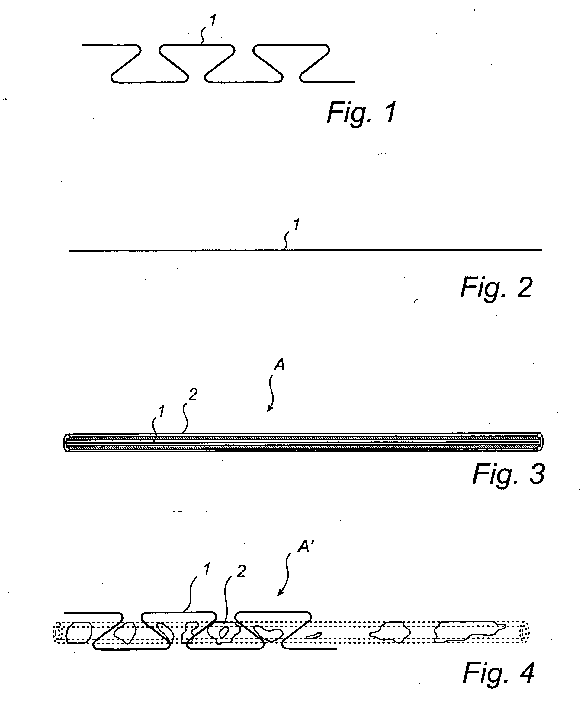
[0107] FIGS. 1 to 4 show the principle of delayed shortening according to the invention.

[0108] In FIG. 1, a shape-changing member 1, here in the form of a thread 1, made of or at least in part including a shape memory material is shown having a curved shape. This shape is the original shape that the shape-changing member 1“remembers” and will assume when the temperature thereof passes a certain threshold, e.g. exceeds 30.degree. C.

[0109]FIG. 2 shows the shape-changing member 1 of FIG. 1 having been straightened by stretching to a substantially straight shape.

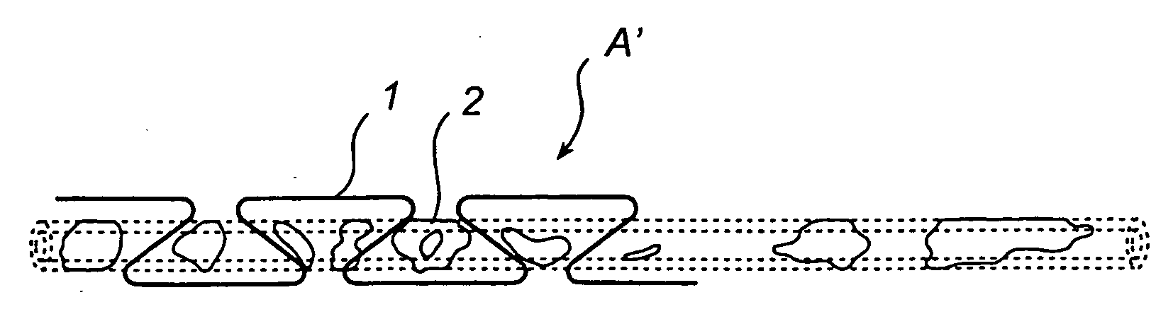
[0110]FIG. 3 illustrates an embodiment of a device according to the invention, where the device is in its non-activated state of shape A. More specifically, by covering the stretched and straight shape-changing member 1 in FIG. 2 with a delay means 2, here in the form of a tube 2 having a sufficiently small inner cross-section, the stretched shape of the shape-changing member 1 can be maintained even when the device is implan...


PUM

PropertyMeasurementUnit
temperaturesaaaaaaaaaa
temperatureaaaaaaaaaa
radius of circumferenceaaaaaaaaaa

Abstract

A delivery system for delivering a prosthetic heart valve to a native valve site within the human vasculature. The prosthetic valve is disposed on a balloon at the end of a balloon catheter. The balloon catheter passes through a delivery sleeve assembly and handle. A pull wire travels from the handle to a distal end of the delivery sleeve assembly. Actuation of the handle pulls on the pull wire, which causes openings in a slotted tube of the delivery sleeve assembly to close, thus causing the delivery sleeve assembly to bend. A stretchable cover is placed over the slotted tube for biasing the steerable catheter toward a straight position. Once advanced to the native valve site, the prosthetic valve is deployed by inflating the balloon.

Description

CROSS-REFERENCE TO RELATED APPLICATION [0001] The present application is a divisional of co-pending, commonly assigned U.S. patent application Ser. No. 10 / 141,348, filed on May 9, 2002, which is incorporated by reference herein in its entirety.TECHNICAL FIELD OF THE INVENTION [0002] The present invention relates to a medical device for providing a change of shape in a part of the body of an organism. The invention further relates to a device and a method for reshaping a body vessel, and a device and a method for restraining growth of a body organ of an organism. BACKGROUND OF THE INVENTION [0003] At present the treatment of mitral annulus dilatation and other mitral insufficiencies consists of either repair or mitral valve replacements. Both methods require open-heart surgery, by the use of total cardiopulmonary by-pass, aortic cross-clamping and cardioplegic arrest. To certain groups of patients, open-heart surgery is particularly hazardous and therefore a less invasive method for ...

Claims


Application Information

Patent Timeline
Patent Type & Authority Applications(United States)
IPC IPC(8): A61F2/06A61F2/02A61F2/04A61F2/07A61F2/24A61F2/26A61F2/82A61F2/848
CPCA61F2/07A61F2/2451A61F2/2481A61F2/26A61F2002/043A61F2002/072A61F2002/826A61F2002/828A61F2002/8483A61F2210/0004
Inventor SOLEM, JAN OTTOKIMBLAD, PER OLA
Owner EDWARDS LIFESCIENCES AG
Why Eureka
Try Eureka