Braided stent to be implanted in a blood vessel

a braided stent and blood vessel technology, applied in the field of braided stents to be implanted in blood vessels, can solve the problems of correspondingly reversed length reduction upon expansion of braided stents, and affecting the effect of length

Inactive Publication Date: 2006-08-17
JOTEC
View PDF13 Cites 138 Cited by
  • Summary
  • Abstract
  • Description
  • Claims
  • Application Information

AI Technical Summary

Benefits of technology

[0029] In view of the above, an object of the present invention is to make avail-able a stent which, on the one hand, anchors securely in the stenosed area, and, on the other hand, effectively prevents detachment of plaque and the latter's entry into the blood stream as emboli.

Problems solved by technology

A disadvantage of braided stents of this kind is generally that they ex-perience a considerable change in length upon stretching, the change in length being all the more pronounced the greater the original diameter and the smaller the original braiding angle.
The correspondingly reversed reduction in length upon expansion of the braided stent is, however, often seen as a disadvantage.
A further problem associated with braided stents is that the radial force and stiffness decline considerably even upon slight elongation of the stent, with the result that the exact dimensioning and positioning of a braided stent is more critical than in stents which do not shorten upon expansion.
This leads to a hard, brittle inner layer which constricts the blood stream more and more and thereby reduces the supply of blood to the brain.
If an occlusion occurs, this results in a far-reaching stroke of the affected half of the brain and irreversible brain damage or even death.
The main complication of percutaneous angioplasty with subsequent stent implantation is caused, however, by the detachment of particles of the brittle inner layer, so-called plaque, which are entrained as emboli into regions of the brain, where they may trigger a local stroke with sometimes severe and irreversible brain damage.
After their insertion and release within the stenosis, these stents in many cases do not develop a sufficient radial force to attain the shape in which they were manufactured.
However, these cerebral protection systems entail a further intervention, often with clinical and symptom-related implications for the patients.
Moreover, however, particles of plaque that have already loosened may also become detached several days after the stent implantation and may pass through the meshes of a conventional stent into the blood stream and thus trigger serious strokes.
However, this “ensheathed” stent has a whole series of disadvantages, in particular for the proposed application.
First, the elastic membrane surrounding it prevents anchoring of the stent in the wall of the blood vessel, with the result that there is a risk of its changing position and losing its protective effect.
Moreover, the known stent is expen-sive and complicated to produce, which fact is attributable to the additionally required elastic membrane.
Given the demand that this stent should not shorten during expansion, it can be manufactured only by technically complex means, with the result that its production is very cost-intensive.
Comparable problems are seen in conical areas of vessels, for example at the carotid bifurcation.
A disadvantage of this stent is that it does not provide any effective pro-tection against detachment of plaque, and, in addition, even the excessively high pressure on the vessel wall in the stenosed area cannot prevent extremely small particles of plaque from detaching and passing into the blood stream through the meshes in the individual rings.

Method used


Image

  • Braided stent to be implanted in a blood vessel
  • Braided stent to be implanted in a blood vessel
  • Braided stent to be implanted in a blood vessel

Examples


Embodiment Construction

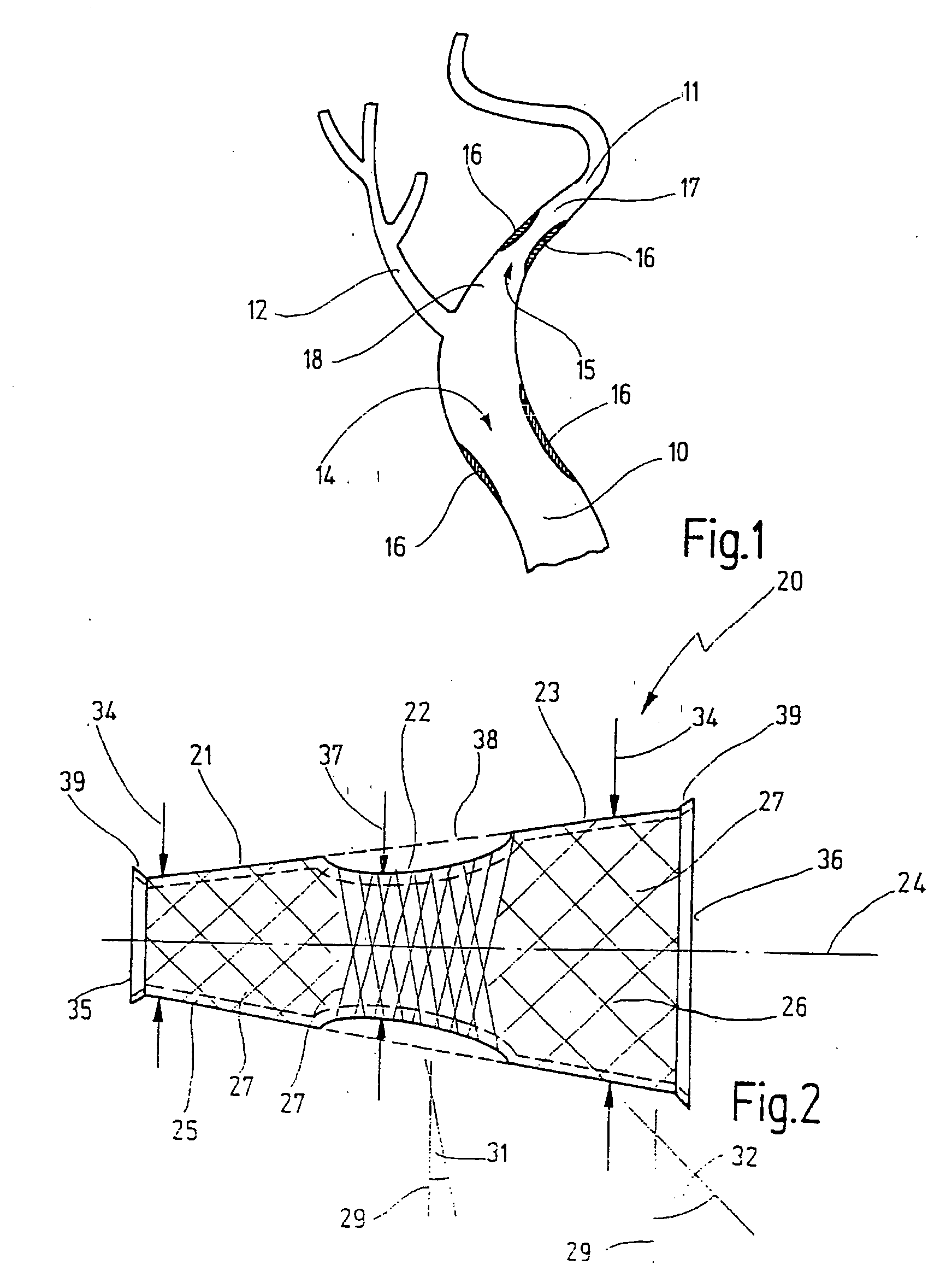
[0069]FIG. 1 shows the geometric situation at the carotid bifurcation in a human. The common carotid artery 10 merges here into the internal carotid artery 11, with the external carotid artery 12 branching off. A stenosis 14 in the common carotid artery and a stenosis 15 in the internal carotid artery 11 are indicated by hard, brittle areas 16. It will be noted that the internal carotid artery 11 has a smaller internal diameter in an area 17 in the distal direction from the stenosis 15 than it does in an area 18 in the proximal direction from the stenosis 15.

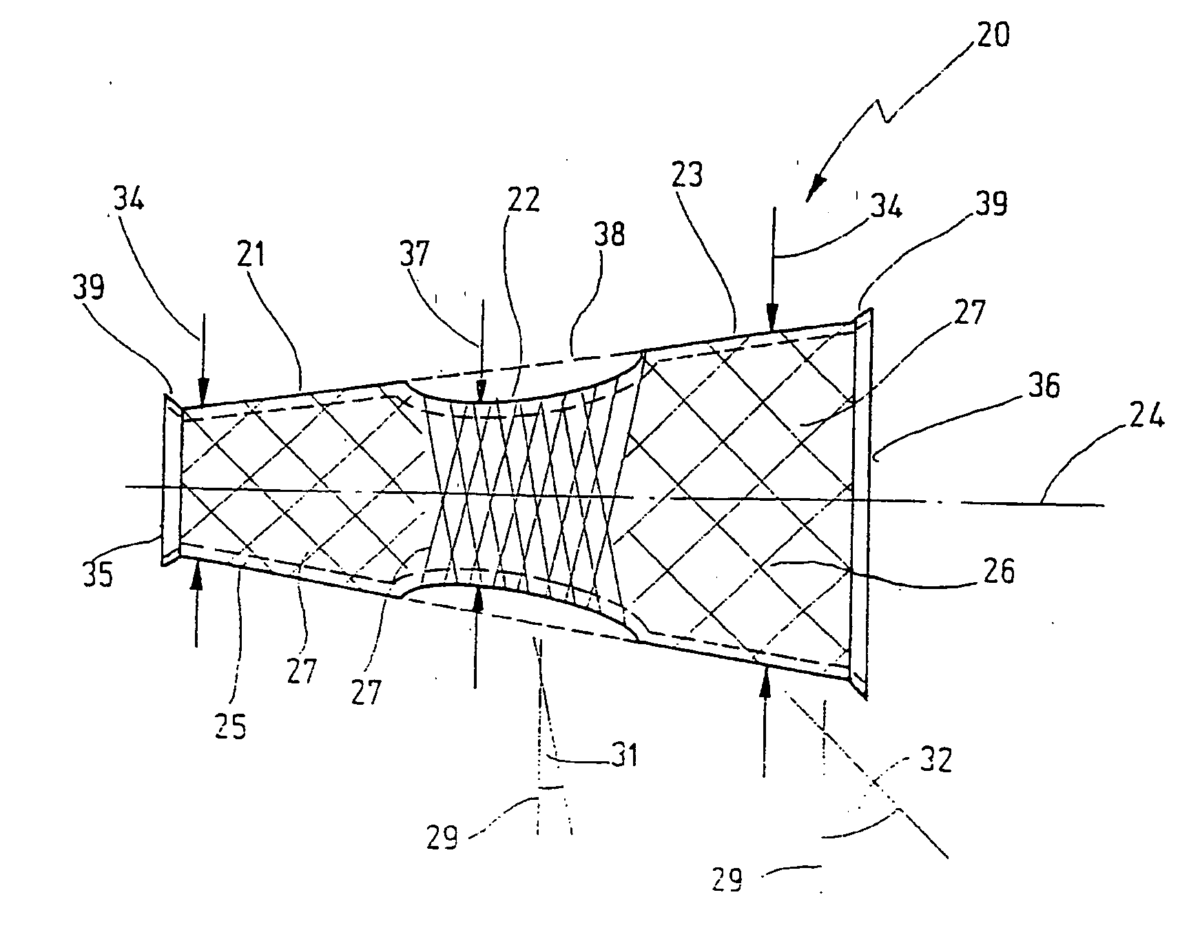
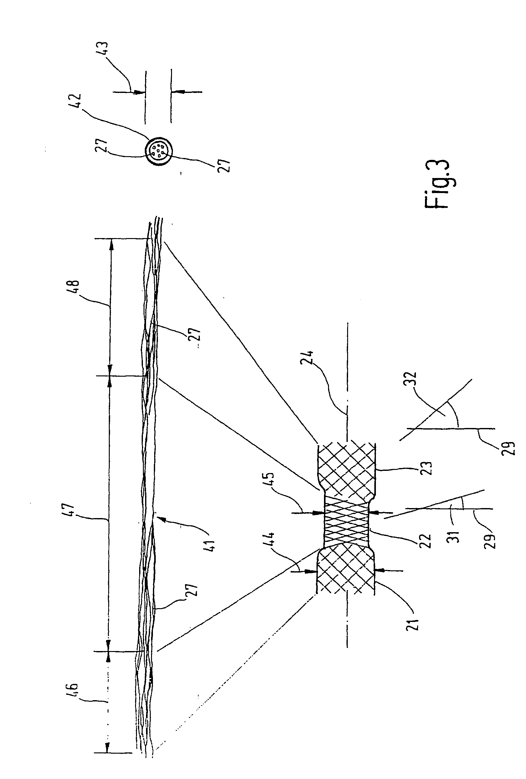
[0070]FIG. 2 shows a braided stent 20 according to the invention which is intended to be inserted into the area of the stenosis 15 in FIG. 1. The braided stent 20 has a distal portion 21, a central portion 22 and a proximal portion 23 arranged one after the other in the longitudinal direction 24 of the braided stent 20.

[0071] The braided stent 20 has a hollow body whose circumferential surface indicated by 25 is made from a br...


PUM


Abstract

A braided stent to be implanted in a blood vessel comprises a hollow body which is stretchable in its longitudinal direction and whose circumferential surface is formed by a braid of a multiplicity of filamentary elements which, in the expanded state of the braided stent, intersect a plane, perpendicular to the longitudinal direction, at a braiding angle. The braided stent has a smaller braiding angle in a central portion than in its distal and proximal portions which adjoin the central portion in the longitudinal direction.

Description

CROSS-REFERENCE TO RELATED APPLICATIONS [0001] This is a continuation application of International Patent Application PCT / EP / 2004 / 008172, filed Jul. 22, 2004, designating the United States and published in German as WO 2005 / 011527 A1, which claims priority to German application number 103 35 649.5, filed Jul. 30, 2003. The contents of these documents are incorporated herein by reference.TECHNICAL FIELD [0002] The present invention relates to a braided stent to be implanted in a blood vessel, in particular in the carotid artery, with a hollow body which is stretchable in its longitudinal direction and whose circumferential surface has a braid comprising a multiplicity of filamentary elements which, in the expanded state of the braided stent, intersect a plane, perpendicular to the longitudinal direction, at a braiding angle. BACKGROUND ART [0003] A braided stent of this kind is known from the document DE 197 50 971 A1. [0004] A stent is understood as a radially expandable endoprosthe...

Claims


Application Information

Patent Timeline
Patent Type & Authority Applications(United States)
IPC IPC(8): A61F2/06A61F2/00A61F2/82A61F2/90
CPCA61F2/90A61F2002/823A61F2230/0078A61F2250/0039A61F2250/0018D10B2101/20D10B2401/046D10B2403/0333D10B2509/06D04C1/06
Inventor KAUFMANN, RALFBOGENSCHUETZ, THOMAS
Owner JOTEC
Why Eureka
Try Eureka