Electric oven

a technology of electric ovens and ovens, which is applied in the field of electric ovens, can solve the problems of failure to properly cook food, failure to properly transmit heat from the heater to the food, and heat may be heated or burned partially by the heater, so as to prevent overheating of components, improve the structure, and improve the effect of heat transmission

Active Publication Date: 2006-08-24
LG ELECTRONICS INC
View PDF27 Cites 27 Cited by
  • Summary
  • Abstract
  • Description
  • Claims
  • Application Information

AI Technical Summary

Benefits of technology

[0011] An object of the present invention is to provide an electric oven, which has an improved structure for uniform transmission of heat from a heater to food in the cooking cavity.
[0012] Other object of the present invention is to provide an electric oven, which has an improved structure for preventing overheating of components starting from a heater, effectively.
[0013] Another object of the present invention is to provide an electric oven, which has an improved cooling structure for preventing the door from involved in temperature rise due to a cooking cavity temperature.
[0022] In other aspect of the present invention, there is provided a method for controlling an electric oven for preventing overheating of heaters and a cooking chamber. The method includes making a halogen heater and a ceramic heater to generate heat in starting cooking, the halogen heater and the ceramic heater being provided in an upper part of an inner case having a cooking cavity formed therein, measuring a temperature of the halogen heater, and comparing the measured temperature of the halogen heater and a preset temperature, to make a sheath grill heater in the cooking cavity to generate heat, if the temperature of the halogen heater is lower than the preset temperature, and to cut off power to the sheath grill heater, if the temperature of the halogen heater is higher than the preset temperature.
[0029] In further aspect of the present invention, there is provided an electric oven and a door having an improved structure for preventing overheating. The electric oven includes an outer case, an inner case, a fan between the inner case and the outer case, and a door mounted in a front part of the outer case for opening / closing the door. The outer case has air suction holes and air discharge holes formed therein, and the inner case therein. The inner case has a cooking cavity formed therein, and the fan draws air through the air suction holes and discharges the air through the air discharge holes. The door has an air inlet hole in one side of a door frame for introduction of air circulated by the fan, an air outlet hole in the other side of the door frame for discharging the air to an outside of the electric oven, and an air passage in the door to make the air inlet hole and the air outlet hole in communication.

Problems solved by technology

However, since the heater has a very high temperature, the heater may heat, or burn the food partially, when the heater is arranged close to a tray in the cooking cavity.
On the other hand, when the heater is arranged far from the tray in the cooking cavity, a failure in proper transmission of the heat from the heater to the food may be caused, to fail to properly cook the food.
Moreover, since the heater has a very high temperature, there is a risk of overheating if the heater is not cooled, effectively.
The overheating of the heater may shorten a lifetime of the heater and cause failure of operation and accidents coming from negligence of safety.
Because the door is always exposed to the user, it is likely that the user is burned or an accident coming from negligence of safety occurs, when the door happens to come into contact with the user.

Method used


Image

  • Electric oven
  • Electric oven
  • Electric oven

Examples


first embodiment

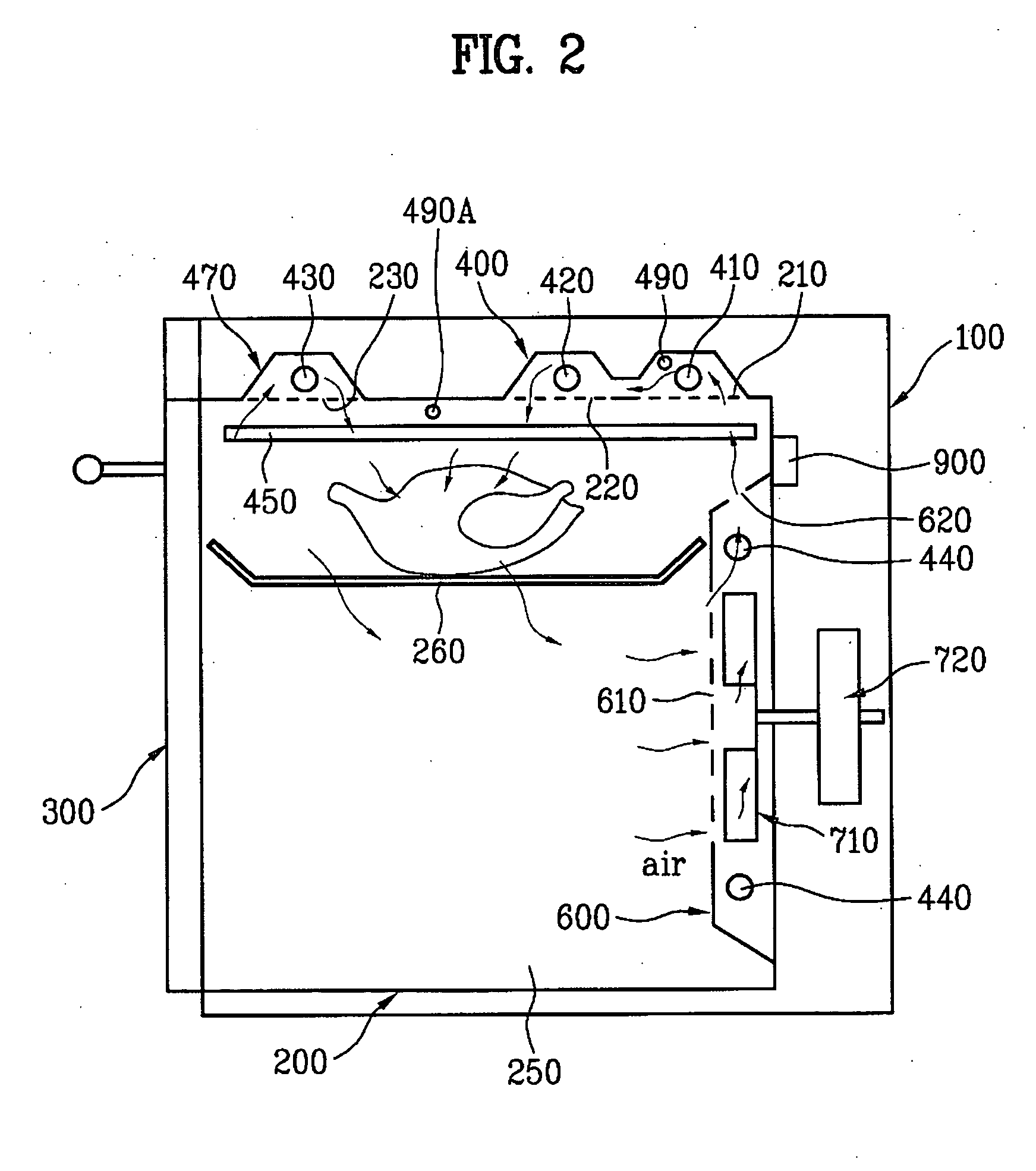
[0049] In the meantime, the present invention provides a structure for solving the problems. FIG. 2 illustrates a diagram showing an electric oven in accordance with a first preferred embodiment of the present invention.

[0050] Referring to FIG. 2, the electric oven includes an outer case 100, an inner case 200, a heater cover 400, at least one heater, a fan housing 600, and a fan 710. The outer case 100 has an opened front, to which a door 300 is rotatably mounted. The inner case 200, provided in the outer case 100, has an opened front part opened / closed by a door 300. As shown in FIG. 2, the inner case 200 forms a cooking cavity 250, having a tray 260 therein for placing food to be cooked thereon. Of course, the tray 260 may be rotatable. The electric oven further includes a magnetron 900 for providing the cooking cavity 250 with microwaves to heat the food.

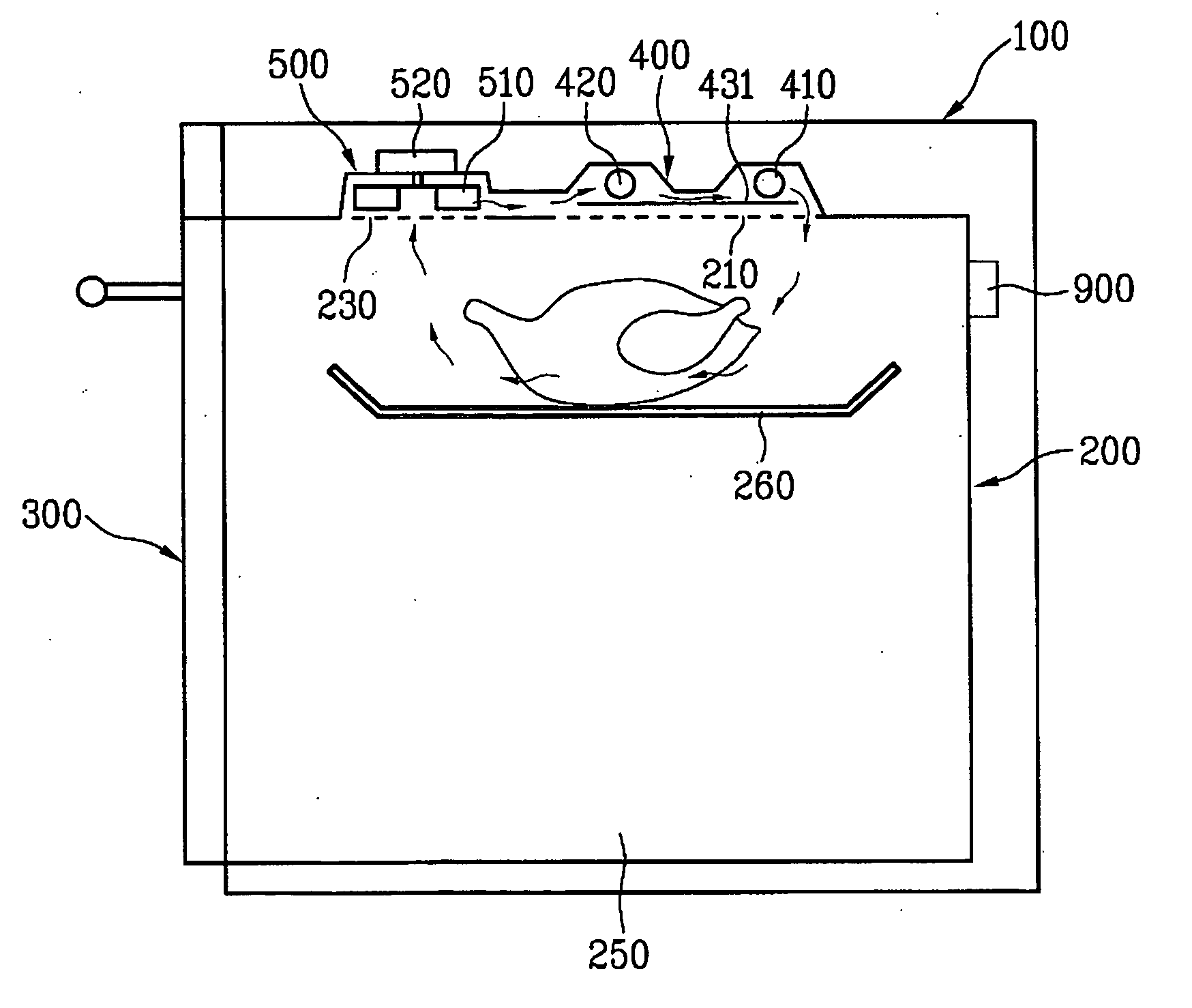
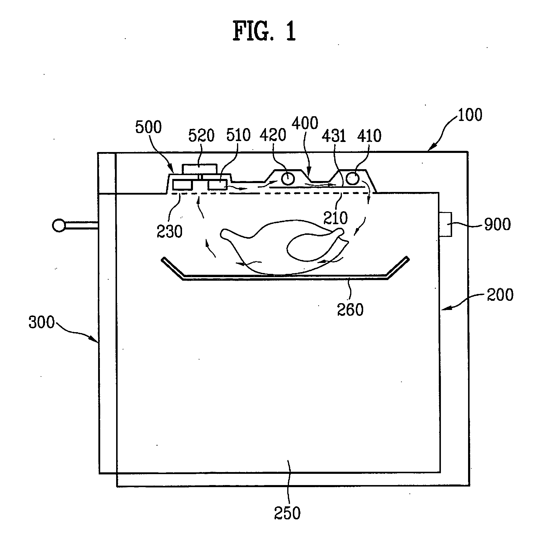
[0051] Referring to FIG. 2, there are a plurality of holes 210 and 220 in the upper part of the inner case 200. As shown in F...

second embodiment

[0094] There may be a fifth heater 450 of sheath grill heater in an upper part of the cooking cavity 250, and, though not shown, there may be a fourth heater in the fan housing 600 like the Like the embodiment in FIG. 2, there may be a temperature sensor at a position adjacent to the first heater 410 and / or a temperature sensor in the cooking cavity 250.

[0095] While descriptions of the components, similar to the descriptions made with reference to FIGS. 2 and 4, are omitted, the operation of the electric oven of the variation of the second embodiment will be described, taking a case when all components are provided as shown in FIG. 5 as an example.

[0096] When the power is provided to the electric oven, the first heater 410 and the second heater 420 generate heat to heat the food in the cooking cavity 250. At the same time, the second fan 710 draws air from the cooking cavity 250 and supplies the air to the first heater 410 and the second heater 420, to cool the heaters 410 and 420...

third embodiment

[0105] the present invention provides a structure for solving the foregoing problem. FIG. 8 illustrates a section showing a door of an electric oven in accordance with a third preferred embodiment of the present invention, FIG. 9 illustrates a diagram showing an electric oven having the door in FIG. 8 applied thereto in accordance with a third preferred embodiment of the present invention, and FIG. 10 illustrates a perspective view showing an air flow in the electric oven in FIG. 9.

[0106] Referring to FIGS. 8 and 9, the electric oven includes an outer case 100, an inner case 200, a door 300, a fan 800, and an outfit chamber 170. As can be noted in comparison of FIGS. 6 and 9, the third embodiment electric oven is similar to the electric oven described with reference to FIG. 6, except that the door 300 in the third embodiment, mounted to a front part of the outer case 100 for opening / closing the cooking cavity 250, has an improved structure better than the door shown in FIG. 6. Accor...


PUM


Abstract

An electric oven includes a cooking cavity surrounded by an inner case and being openable by a door; a first heater for heating the cooking cavity; at least one supplemental heater for heating the cooking cavity; and a controller operating the first heater to generate heat when starting cooking and selectively operating the at least one supplemental heater during cooking.

Description

[0001] This application is a Continuation-In-Part of copending application Ser. No. 10 / 733,399 filed on Dec. 12, 2003, the entire contents of which are hereby incorporated by reference. In addition, this application claims the benefit of the Korean Application Nos. P2002-0080350 filed on Dec. 16, 2002, P2002-0080351 filed on Dec. 16, 2002, and P2002-0086898 filed on Dec. 30, 2002, which are hereby incorporated by reference.BACKGROUND OF THE INVENTION [0002] 1. Field of the Invention [0003] The present invention relates to electric ovens, and more particularly, to an electric oven, which has an improved structure for smooth circulation of air inside of the electric oven. [0004] 2. Background of the Related Art [0005] In general, the electric oven cooks food, not by burning gas like a gas oven, but by elevating a temperature inside of the oven with electricity or by directing a microwave to food. [0006] The electric oven is favored by consumers in light of no generation of flame, and ...

Claims


Application Information

Patent Timeline
Patent Type & Authority Applications(United States)
IPC IPC(8): A21B1/22A21B1/00F27D11/00F24C7/06F24C7/08F24C15/00F24C15/04F24C15/32
CPCF24C7/06F24C7/087F24C15/006F24C15/04F24C15/325H05B6/642H05B6/6482H05B6/6414H05B6/6485
Inventor KIM, HAG SINKANG, MYEONG YEOL
Owner LG ELECTRONICS INC
Why Eureka
Try Eureka