Height-adjusting device and support for optical systems, which comprises height-adjusting devices

a technology of height adjustment and optical system, applied in the direction of machine supports, instruments, furniture parts, etc., can solve the problems of large floor surface, unfavorable hand position of users, and inability to provide height adjustment, etc., and achieve the effect of improving force transmission

Active Publication Date: 2006-08-24
LEICA MICROSYSTEMS CMS GMBH
View PDF12 Cites 11 Cited by
  • Summary
  • Abstract
  • Description
  • Claims
  • Application Information

AI Technical Summary

Benefits of technology

[0020] Another advantage of the invention is that it provides a support for an optical system provided with at least three height-adjusting devices. The height-adjusting devices can be fastened directly to the bottom of the optical system. As an alternative, the height-adjusting devices can be disposed in the base of a support for the optical system. The support for the optical system is provided with a left and a right hand rest, the left and the right hand rest being fastened to the base by means of a hinge. Each height-adjusting device has a socket surrounded on all sides by a rotary wheel. The rotary wheel also surrounds a foot. On the rotary wheel there are provided a first thread and a second thread having complementary inclinations. The socket cooperates with the first thread on the rotary wheel, and the foot cooperates with the second thread on the rotary wheel so that the height adjustment takes place without a rotary movement of the foot.
[0021] The support for the optical system consists of the base which in turn consists of the bottom and a surrounding wall. The contour of the bottom corresponds to the contour of the bottom of an optical system that is located on or is connected to the support. The surrounding wall has at least three recesses through which the rotary wheel partly penetrates. As a result, the height-adjusting device is not completely visible from the outside, and only the rotary wheel can be actuated to achieve a height adjustment of the optical system or of the support.
[0022] To actuate the rotary wheel, each rotary wheel is provided with a ribbing to obtain improved force transmission from the hand of the user to the rotary wheel. To persons skilled in the art it is evident that the ribbing which extends all around can also be in the form of a friction-enhancing rubber coating.
[0023] The height-adjusting devices are disposed on the base of the support at the corner points of an equilateral triangle. The two height-adjusting devices disposed at base of the equilateral triangle are connected to each other by a transmission element. In this manner, a synchronous displacement of said two height-adjusting devices is achieved. It is also conceivable that all height-adjusting devices disposed on the support are coupled by a transmission element.
[0024] The optical system disposed on the support is, for example, a microscope for which an ergonomic work position for the user is to be achieved with the aid of the height-adjusting devices and of the hand rests provided on the support or on the base of the support. Regardless of the adjusted height of the support, the user should be able to assume an ergonomic work position relative to the mechanical operation elements, for example the control knob.
[0025] Other advantageous features of the invention will become evident from the claims below.

Problems solved by technology

The optical systems that hitherto have been commercially available did not provide the possibility of height adjustment so that in this manner they could be adapted to the various ergonomic requirements of the various users.
In addition, the base plate requires a large floor surface which is detrimental when close-by instrument placement on laboratory tables is needed.
Hand rests for the user are not provided so that for a height-adjusted microscope, the user must assume an extremely unfavorable hand position.
For many experiments, tilting the entire microscope is not suitable.
The arrangement, however, is not of a compact design.
Height adjustment by means of a motor is complicated and not well suited for simple and fast adjustment.
The installation bottom support has the drawback that during the adjustment which takes place by rotation, the spherical segments rub against the bottom so that an increased adjustment force is required.

Method used


Image

  • Height-adjusting device and support for optical systems, which comprises height-adjusting devices
  • Height-adjusting device and support for optical systems, which comprises height-adjusting devices
  • Height-adjusting device and support for optical systems, which comprises height-adjusting devices

Examples


Embodiment Construction

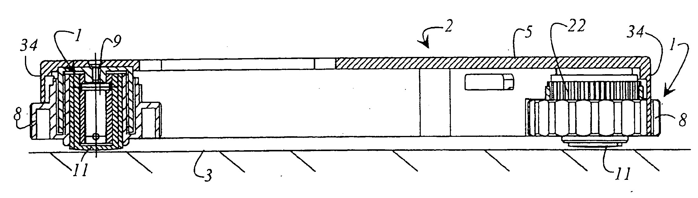
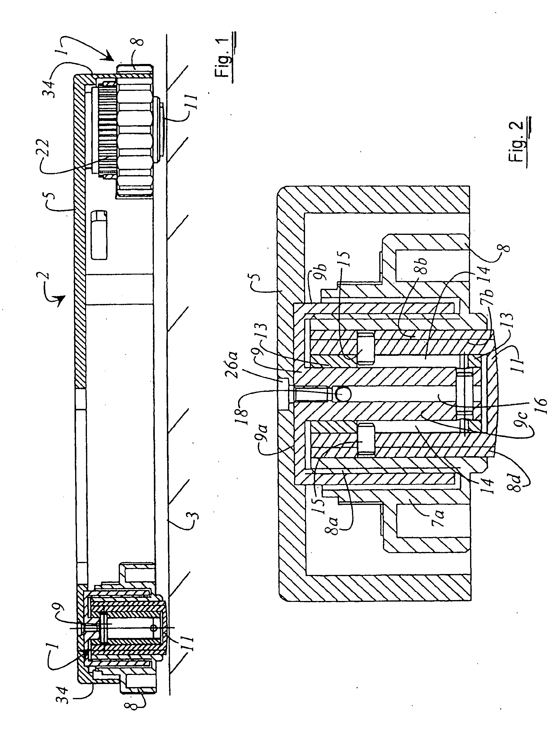
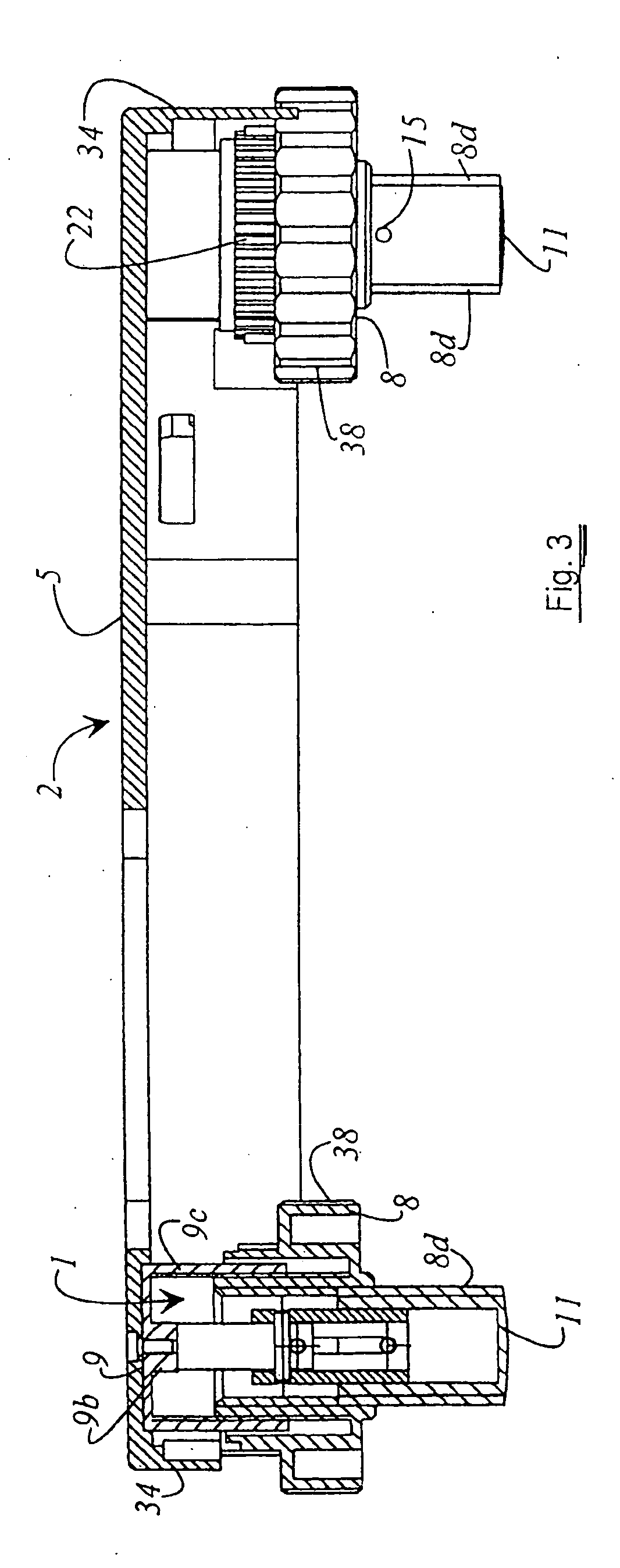
[0037]FIG. 1 shows a cross section of an arrangement 2 wherein there are disposed several height-adjusting devices 1. Arrangement 2 defines a housing open toward a mounting surface 3, the housing comprising a bottom 5 and a surrounding wall 34. Each height-adjusting device 1 comprises a foot 11 which is in contact with mounting surface 3. Height-adjusting device 1 is provided with a rotary wheel 8 whereby the height adjustment is achieved. To increase the friction between the user's hand and rotary wheel 8, each rotary wheel 8 is provided with a ribbing 38. Naturally, other means, for example a rubber coating, may be used to increase friction. Moreover, in the embodiment shown in FIG. 1 each of the rotary elements 8 is provided with a toothed element 22 cooperating with a transmission element 24 (see FIG. 8).

[0038]FIG. 2 shows a cross section of a device 1 wherein the height adjustment has not been made. Height-adjusting device 1 comprises a socket 9 comprising a cover 9a, a cylind...


PUM


Abstract

A device for adjusting the height of an arrangement 2 relative to a mounting surface 3 is disclosed. Height-adjusting device 1 is designed so that during height adjustment no friction takes place as a result of rotation of the contact sites of the height-adjusting devices 1 with the mounting surface 3. Height-adjusting device 1 consists of a rotary wheel 8, a socket 9 and a foot 11. The height adjustment of rotary wheel 8 and foot 11 relative to the stationary socket 9 occurs in telescopic manner. Height-adjusting device 1 is designed so that the foot 11 undergoes a displacement twice as large as does rotary wheel 8. A support (30) for an optical system is provided with several height-adjusting devices 1 connected with the bottom 5 of a base 31 of the support 30. On the support 30 there are provided a left and a right hand rest 31a and 31b which are fastened to the base 31 of the support 30 by means of a hinge 32 so that independently of the height adjustment of the support 30, the edges 32a of the left or right hand rest located opposite the hinge always rest on the mounting surface 3.

Description

CROSS REFERENCE TO RELATED APPLICATIONS [0001] This application claims priority of the German patent application 103 13 656.8, filed Mar. 26, 2003, and the International application PCT / EP2004 / 050233, filed Mar. 2, 2004, which are incorporated by reference herein. FIELD OF THE INVENTION [0002] The invention relates to a device for height adjustment. In particular, the invention relates to a device for adjusting the height of an arrangement relative to a mounting surface wherein the device is connected to the base of the arrangement. The device consists of at least two movable elements that can be displaced relative to one another in telescopic manner. Firmly connected with the base is a socket surrounded on all sides by a rotary wheel. The rotary wheel also surrounds a foot. On the rotary wheel there are provided a first and a second thread with complementary inclinations. The socket cooperates with the first thread on the rotary wheel and the foot with the second thread on the rota...

Claims


Application Information

Patent Timeline
Patent Type & Authority Applications(United States)
IPC IPC(8): F16M11/24A47B91/02F16M7/00G02B7/00
CPCA47B91/028F16M7/00
Inventor BENDER, CLAUS
Owner LEICA MICROSYSTEMS CMS GMBH
Why Eureka
Try Eureka