Upper valve part for fittings

Active Publication Date: 2006-08-24
FLUHS DREHTECHN
View PDF14 Cites 3 Cited by
  • Summary
  • Abstract
  • Description
  • Claims
  • Application Information

AI Technical Summary

Benefits of technology

[0007] It is therefore an object of the invention to create an upper valve part for fittings that only allows the positions “completely open” and “completely closed,” and thus reduces the design effort in comparison with known upper valve parts. This object is accomplished in that a locking device that acts radially is provided.
[0008] An upper valve part for fittings, which permits only two positions, namely the position “completely open” and the position “completely closed,” is created with the invention. At the same time, the upper valve part is structured in a simple manner, thereby making the production costs low. Furthermore, the assembly effort for the upper valve part according to the invention is low.

Problems solved by technology

However, the design effort is quite complicated, because of the requirement of a handle that can be moved in the axial direction of the upper valve part, as well as the mechanism for shutting off the valve.
As a consequence, the production of the upper valve part is complicated.

Method used


Image

  • Upper valve part for fittings
  • Upper valve part for fittings
  • Upper valve part for fittings

Examples


Embodiment Construction

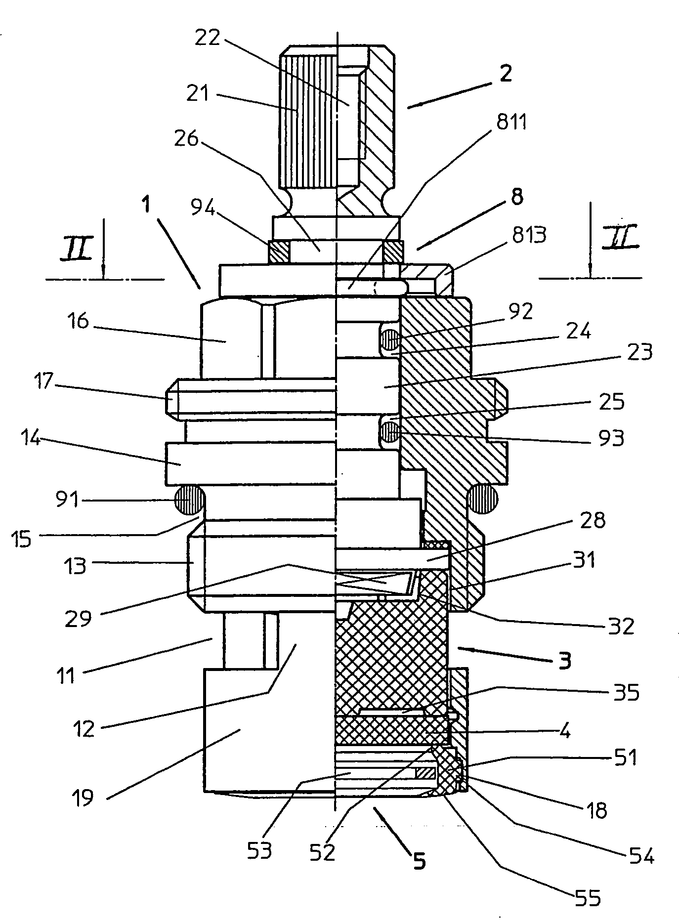
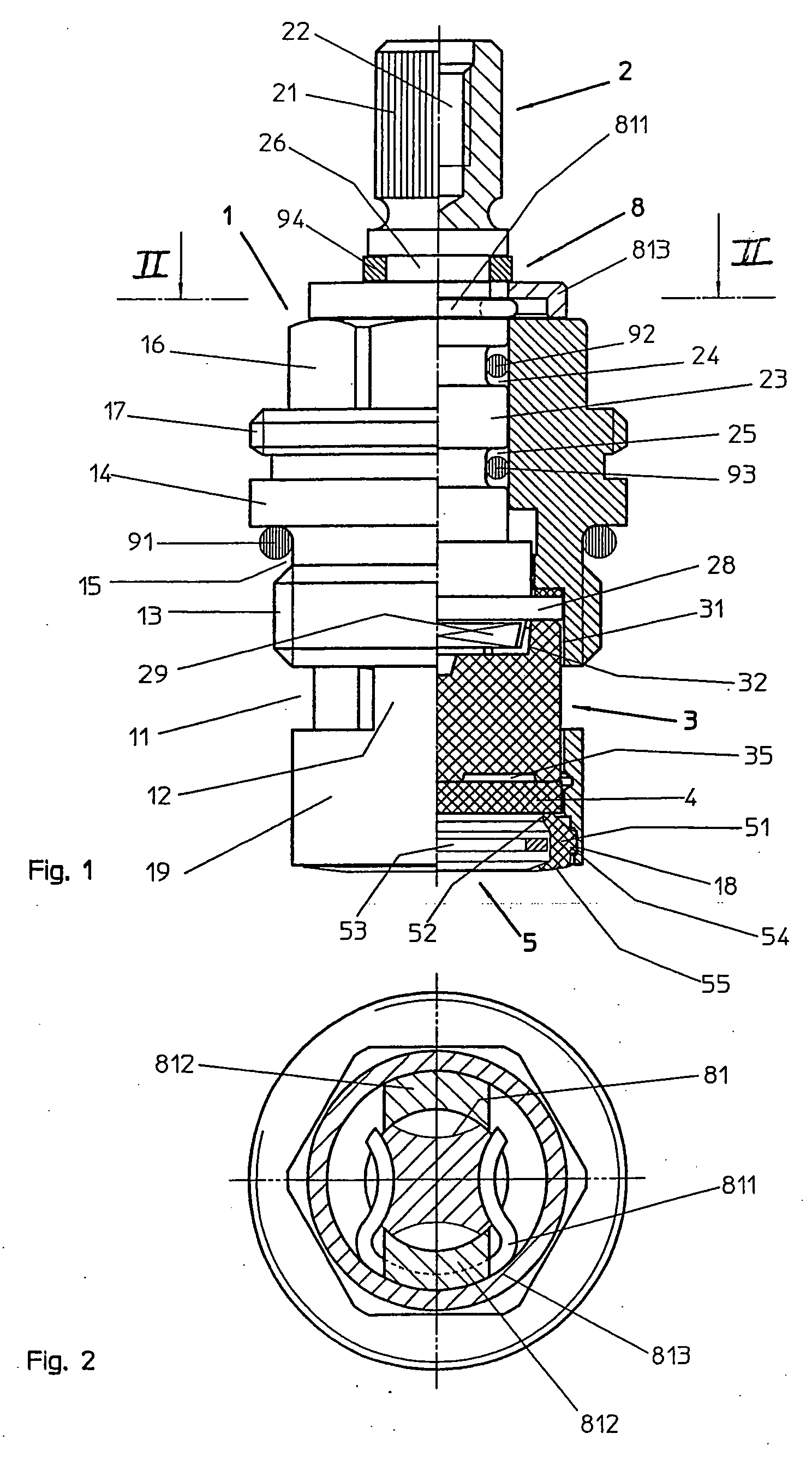
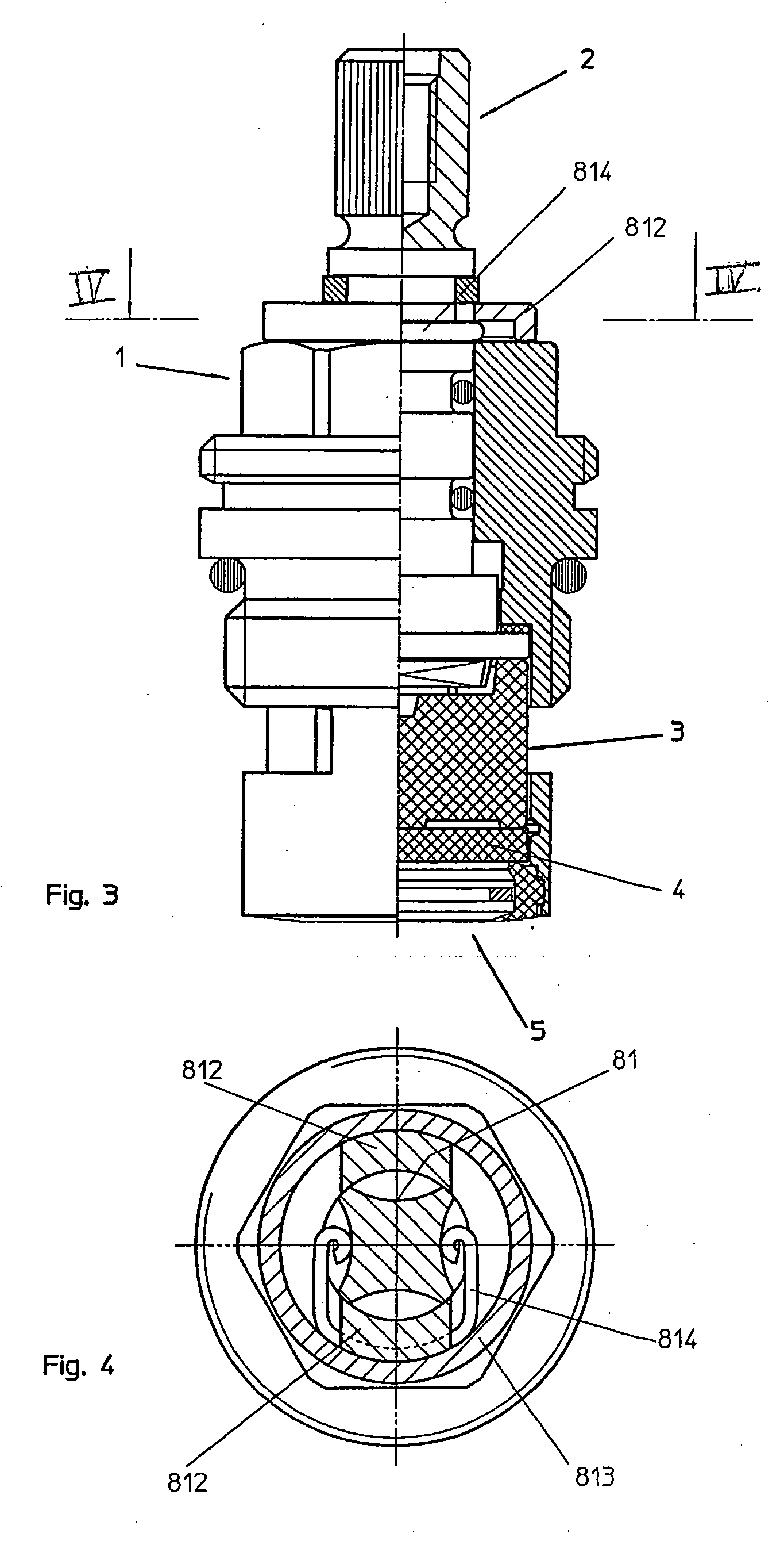
[0040] Referring now in detail to the drawings, the upper valve parts selected as exemplary embodiments have a head piece 1, 10, through the center of which a spindle 2, 20, guided radially in it, passes. A control disk 3, 30 is connected with the spindle 2, 20, with a positive lock, and radially guided in the head piece 1. On the side of the control disk 3, 30 that faces away from the spindle 1, an inlet disk 4, 40 is provided on the head piece 1, 10, followed by a seal ring 5 that comes to rest on the valve seat of a fitting (not shown). In the embodiments according to FIGS. 13 to 18, the upper valve parts have a disk guide 60, in each instance, which is disposed in the head piece 10 so as not to rotate, and in which the spindle 20 is guided. Furthermore, a cap sleeve 70 is disposed around the head piece 10. All of the upper valve parts are provided with a locking device 8, in each instance.

[0041] In the following, the structure of the upper valve parts according to FIGS. 1 to 12...


PUM


Abstract

An upper valve part for fittings has a head piece through which a spindle passes, means for shut-off, and a seal that comes to rest on the fitting. A radially acting locking device is provided.

Description

BACKGROUND OF THE INVENTION [0001] 1. Field of the Invention [0002] The invention relates to an upper valve part for fittings, having a head piece through which a spindle passes, and means for shut-off, and having a seal that comes to rest on the fitting. [0003] 2. The Prior Art [0004] The exit of media from fittings is controlled using upper valve parts. For this purpose, the upper valve part is screwed into the housing of a fitting by its head piece, and a handle or lever is set onto its spindle. In the case of known upper valve parts (see German Patent Nos. DE 32 07 895 C2, DE 36 38 180 C2, and DE 87 15 044 U1), two disks for controlling the through-flow are provided, in each instance. The disks are produced from ceramic material. One of the two disks, the control disk, is disposed to rotate in the upper valve part, using a driver that is connected with the spindle. The other disk, the inlet disk, is a fixed valve seat disk, also referred to as a fixed disk. When the control disk...

Claims


Application Information

Patent Timeline
IPC IPC(8): F16K35/00F16K3/08
CPCF16K3/08Y10T137/86549
Inventor SCHWARZER, PETERTHURAU, FRIEDRICH
Owner FLUHS DREHTECHN
Why Eureka
Try Eureka