Adaptive antenna reception device having preferable reception quality of directivity beam from the initial stage

a directivity beam and antenna reception technology, applied in direction finders using radio waves, instruments, polarisation/directional diversity, etc., can solve the problems of affecting the reception characteristics of user signals, beams cannot be directed in the arrival direction of a desired user signal, and the signal of other users interferes with the signal of a particular user, etc., to achieve good reception characteristics, high accuracy weight, and quick and easy acquisition

Inactive Publication Date: 2006-08-24
NEC CORP
View PDF8 Cites 8 Cited by
  • Summary
  • Abstract
  • Description
  • Claims
  • Application Information

AI Technical Summary

Benefits of technology

[0051] Accordingly, in signal processors that are to begin determination of weight that uses time averaging, a beam direction weight that is acquired quickly and easily can be used until sufficient averaging time has been secured, and after the averaging time has become sufficient, a highly accurate weight that is obtained by time averaging can be used. As a result, the appropriate method of determining beam direction can be selected according to the current conditions both before and after sufficient averaging time has been secured, and a directional beam having good reception characteristics can always be obtained.

Problems solved by technology

In a mobile communication system according to the CDMA (Code Division Multiple Access) method, a radio base station simultaneously receives user signals from a plurality of mobile stations, and signals of other users therefore interfere with the signal of a particular user.
When a non-directional weight is taken as the initial weight, gain is the same for all directions, and as a result, a beam cannot be directed in the arrival direction of a desired user signal.
As a result, when the path timing of a finger changes greatly at the time a finger is newly assigned, or when sufficient averaging time cannot be secured in weight calculation units 61-6L, there is a potential for degradation of the reception characteristics of the user signal.

Method used


Image

  • Adaptive antenna reception device having preferable reception quality of directivity beam from the initial stage
  • Adaptive antenna reception device having preferable reception quality of directivity beam from the initial stage
  • Adaptive antenna reception device having preferable reception quality of directivity beam from the initial stage

Examples


Embodiment Construction

[0065] The following explanation regards the details of embodiments of the present invention with reference to the accompanying figures.

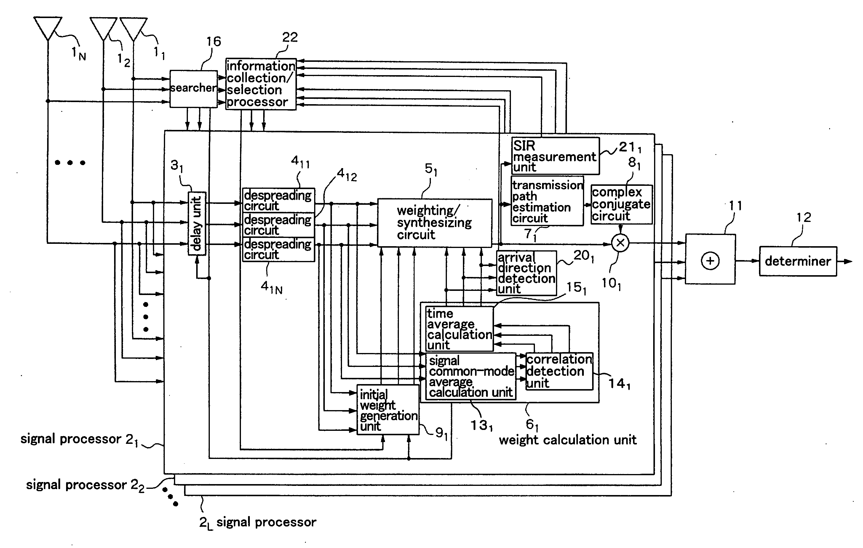
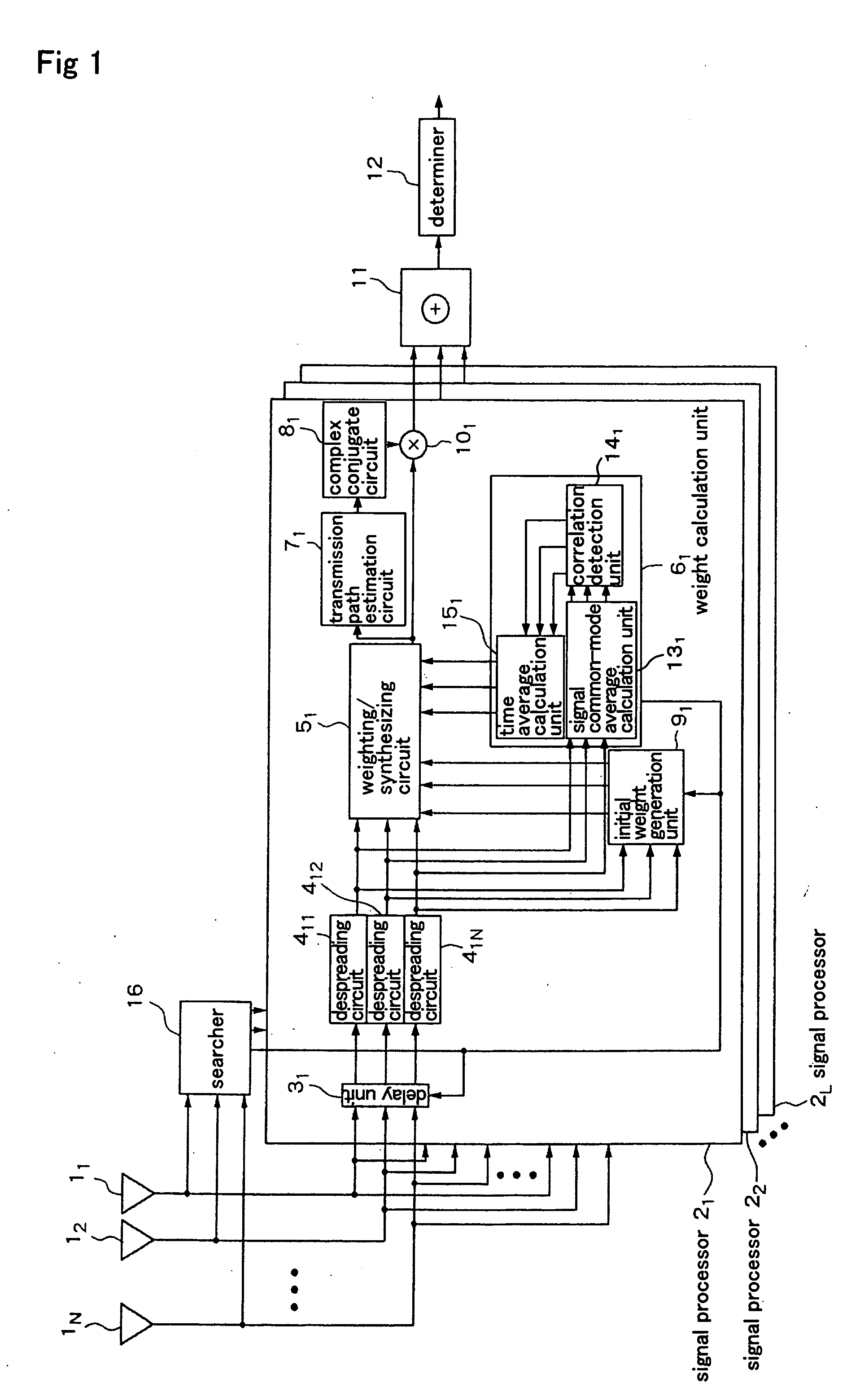
[0066]FIG. 5 is a block diagram showing an example of the configuration of an open-loop controlled adaptive antenna reception device according to the present embodiment. In the adaptive antenna reception device of the present embodiment that is shown in FIG. 5, the number of antennas that make up the adaptive antenna is N (where N is an integer equal to or greater than 2) and the number of synthesized multi-paths is L (where L is a natural number). FIG. 5 shows the circuit portion for receiving the user signal that is received from the mobile station of the kth user (where k is a natural number).

[0067] Referring to FIG. 5, the adaptive antenna reception device includes: antennas 11-1N, signal processors 21-2L, adder 11, determiner 12, searcher 16, and information collection / selection processor 22.

[0068] Signal processor 21 includes: delay unit 31...


PUM


Abstract

An adaptive antenna reception device is disclosed in which a directional beam having excellent reception characteristics can be quickly and easily obtained from the start by selecting an initial beam direction of signal processors that are to begin determination of weight that uses time averaging based on the reception quality and the arrival direction in which the reliability is high for an incoming wave that is received in each signal processor in which sufficient averaging time has been secured. An arrival direction detection unit detects the arrival direction of an incoming wave that is received in each signal processor from weight that is determined by each signal processor in which at least a prescribed time interval has been secured for the averaging time for finding a time average. A SIR measurement unit finds the reception quality of a signal of an incoming wave that is received by weighting and synthesizing in each signal processor in which at least a prescribed time interval has been secured for the averaging time. An information collection/selection processor, based on each arrival direction and each reception quality in each signal processor in which at least a prescribed time interval has been secured for the averaging time, selects the initial beam direction in signal processors that are to begin determination of weight using time averaging.

Description

TECHNICAL FIELD [0001] The present invention relates to an adaptive antenna reception method for weighting each of the antennas that make up an adaptive antenna to receive a signal with superior characteristics, and to a device that uses such a method. BACKGROUND ART [0002] In a mobile communication system according to the CDMA (Code Division Multiple Access) method, a radio base station simultaneously receives user signals from a plurality of mobile stations, and signals of other users therefore interfere with the signal of a particular user. An adaptive antenna is used to receive a desired user signal at a higher gain. [0003] An adaptive antenna is composed of a plurality of antennas and controls amplitude and phase in accordance with a complex number weight that is conferred to the signals that are received by each of the antennas to form directivity. An adaptive antenna is thus capable of suppressing other user signals that constitute interference and of effectively receiving a ...

Claims


Application Information

Patent Timeline
Patent Type & Authority Applications(United States)
IPC IPC(8): H01Q3/00H01Q3/26H04B1/707H04B1/7117H04B1/712H04B7/08H04B7/10H04B7/26H04W16/28
CPCH04B7/0842H04B7/08H04B7/10H04W16/28
Inventor KIMATA, MASAYUKI
Owner NEC CORP
Why Eureka
Try Eureka