Turbine housing of an exhaust gas turbocharger with a variable turbine geometry

a turbine geometry and turbine technology, applied in liquid fuel engines, machines/engines, lighting and heating apparatus, etc., can solve the problems of loss of prestressing force, inability to linearly expand the holding elements beyond the yielding point, and components exposed to high exhaust gas temperatures, so as to achieve reliable continuous operation of the vtg charger

Inactive Publication Date: 2006-08-24
DR ING H C F PORSCHE AG
View PDF2 Cites 10 Cited by
  • Summary
  • Abstract
  • Description
  • Claims
  • Application Information

AI Technical Summary

Benefits of technology

[0004] It is an object of the invention to overcome the above-described disadvantages so that a reliable continuous operation of the VTG charger is guarantied.

Problems solved by technology

Particularly when these VTG chargers are used in the case of Otto engines, these components are exposed to high exhaust gas temperatures.
This may lead to an unacceptable linear expansion of the holding elements beyond their yielding point.
If the holding element is constructed as a fastening screw, this results in a loss of prestressing force.
As a result of loss of prestressing force, the fastening screw now has to absorb all transverse forces occurring because of the engine operation, which, under certain circumstances, may lead to component failure of the fastening screw.

Method used


Image

  • Turbine housing of an exhaust gas turbocharger with a variable turbine geometry
  • Turbine housing of an exhaust gas turbocharger with a variable turbine geometry
  • Turbine housing of an exhaust gas turbocharger with a variable turbine geometry

Examples


Embodiment Construction

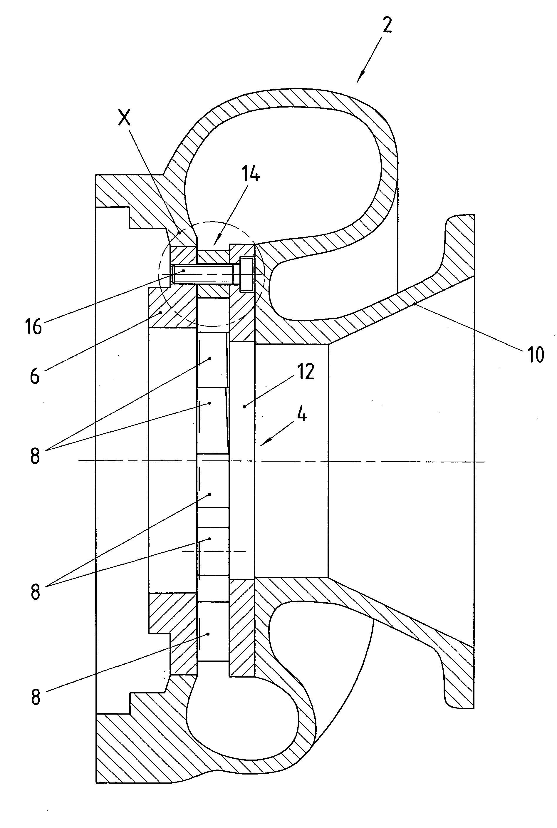
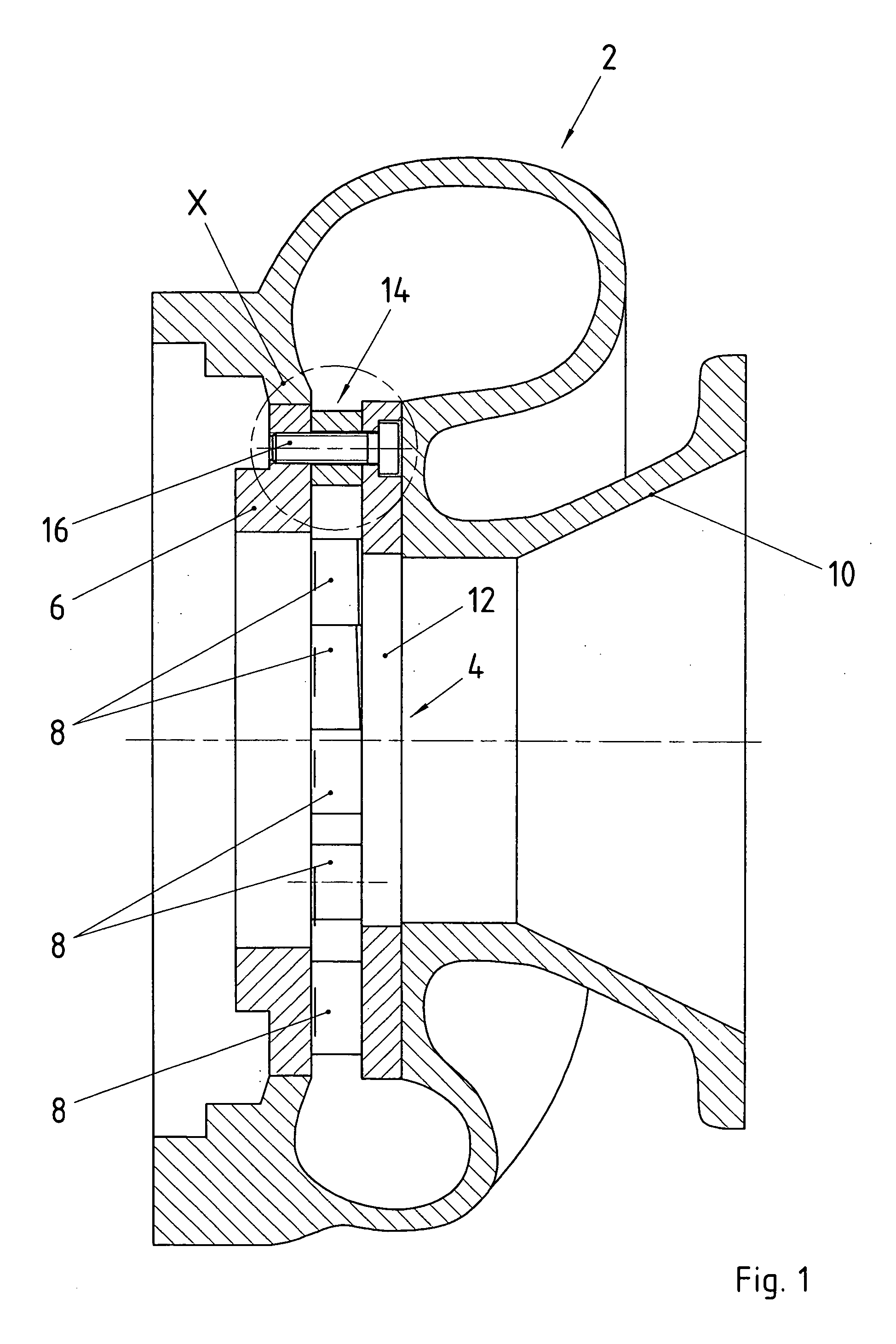
[0016] A vane apparatus 4 is arranged in a turbine housing 2 of a so-called VTG exhaust gas turbocharger. The vane apparatus 4 consists of a support ring 6 to which vanes 8 are fastened which are adjustable for controlling the charge pressure. On their face assigned to the exhaust gas outlet 10, the vanes 8 are bounded by a covering ring 12. Spacing elements, which in the present case are constructed as spacing sleeves 14 and are radially distributed on the circumference of the support and covering ring 6, 12, the axial vane gap is defined. The spacing sleeves 14 are held by fastening elements which in the present embodiment are constructed as fastening screws 16. As an alternative, bolts, pins, or the like are also conceivable as the fastening elements for the spacing sleeves 14.

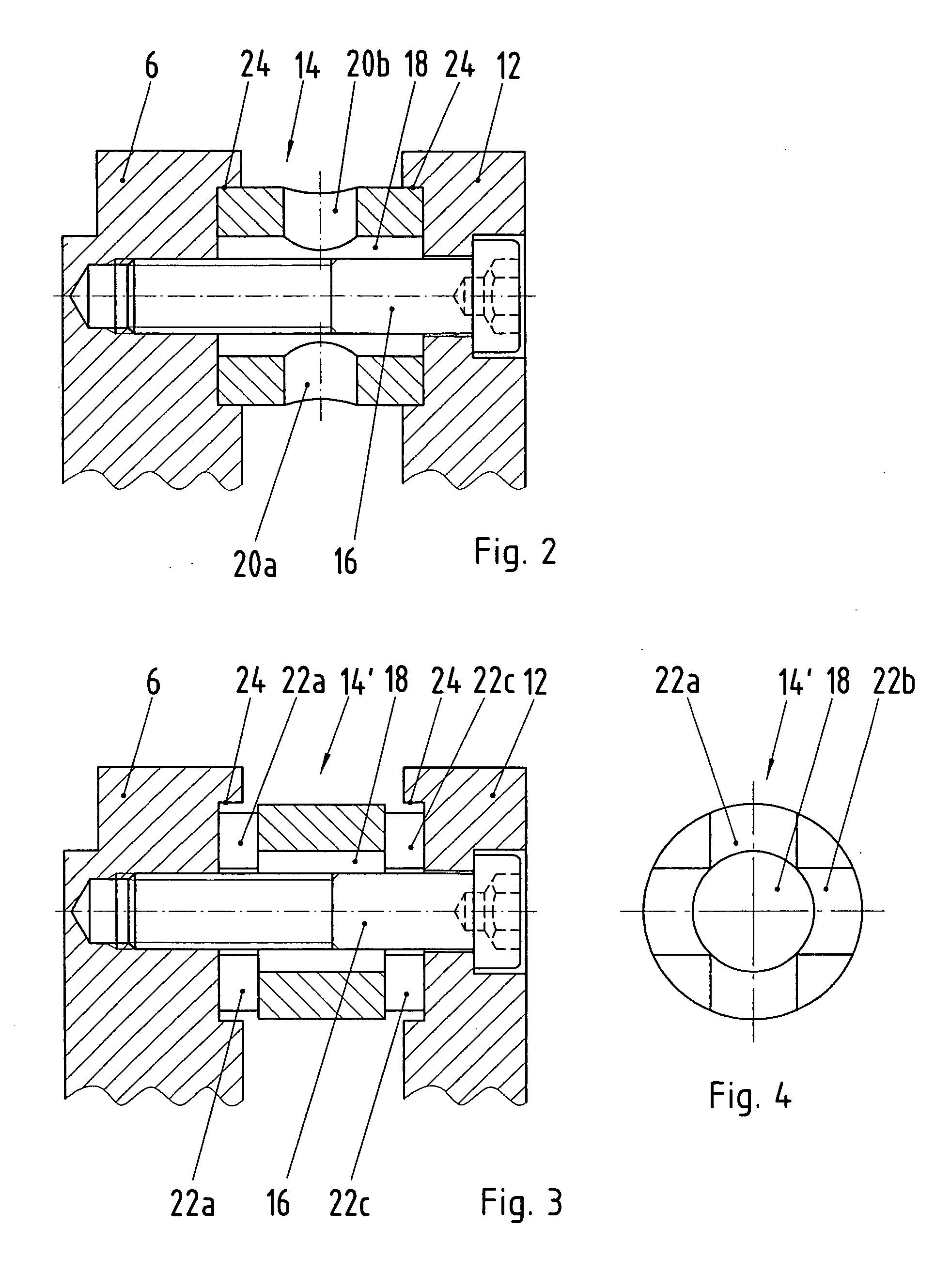
[0017]FIG. 2 shows a first embodiment of a spacing sleeve 14, in the case of which four recesses in the form of bores 20a to 20d are provided which are arranged to be radially offset with respect to one an...


PUM


Abstract

A turbine housing of an exhaust gas turbocharger with a variable turbine geometry is provided, having a support ring to which vanes are fastened which are adjustable for controlling the charge pressure, and having a covering ring for the vanes. The support ring and covering ring are spaced for forming a vane gap by spacing elements which are each penetrated by a holding element which is fastened in the support ring and/or the covering ring. The spacing elements have recesses which, during the operation of the exhaust gas turbocharger, permit a direct action of the exhaust gas flow upon the holding elements.

Description

CROSS-REFERENCE TO RELATED APPLICATION [0001] This application claims priority under 35 U.S.C. §119 to German Application Nos. 10 2004 059 803.7 and 10 2005 001 864.5, filed Dec. 10, 2004, and Jan. 14, 2005, respectively, the entire disclosures of which are hereby incorporated herein by reference. BACKGROUND AND SUMMARY OF THE INVENTION [0002] The invention relates to a turbine housing of an exhaust gas turbocharger with a variable turbine geometry. [0003] Exhaust gas turbochargers, in the case of which the supercharging pressure can be controlled by means of adjustable vanes, are known, for example, from German Patent Document DE 103 12 324 B3. In the turbine housing of such VTG (variable turbine geometry) chargers, a vane apparatus is fastened which consists of a support ring for the vanes, as well as a covering ring which is situated opposite the support ring while maintaining a vane gap distance. For the spacing of the support ring and the covering ring, spacing elements, for ex...

Claims


Application Information

Patent Timeline
Patent Type & Authority Applications(United States)
IPC IPC(8): F01D9/00
CPCF01D17/165F01D25/12F01D25/243
Inventor STERNER, ANDREASRONNEBURGER, RALPHWEINLAND, GUENTHER
Owner DR ING H C F PORSCHE AG
Why Eureka
Try Eureka