
Thermal-type infrared detection element

Inactive Publication Date: 2006-08-24
NEC CORP
View PDF5 Cites 13 Cited by
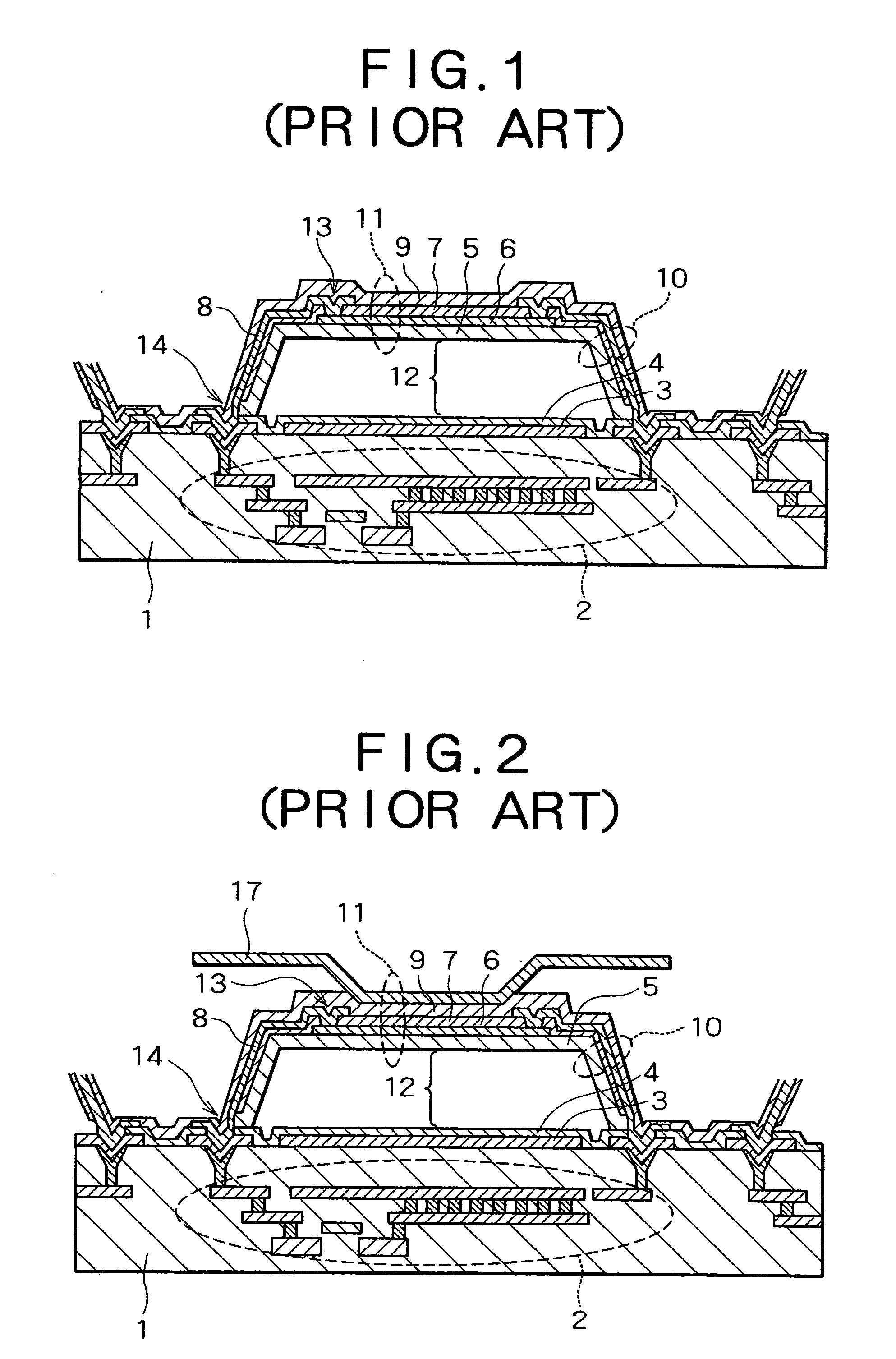
  • Summary
  • Abstract
  • Description
  • Claims
  • Application Information

AI Technical Summary

Benefits of technology

[0009] An object of the present invention is to provide a structure for a thermal-type infrared detection element; specifically, a structure for the infrared absorption body that constitutes the photoreceptor, whereby the absorption efficiency of incident infrared rays is increased, and sensitivity is enhanced.
[0016] Thus, in the present invention, since a convex or concave pattern in which a plurality of substantially congruent projections or holes are arranged at a substantially constant pitch is formed on the surface of the infrared-incident side of the photoreceptor of the thermal-type infrared detection element, reflection of incident infrared rays on the photoreceptor is minimized, and the absorption efficiency of infrared rays can be increased. The sensitivity of the thermal-type infrared detection element can thereby be enhanced.
[0017] As described above, the absorption efficiency of infrared rays incident on the photoreceptor can be increased by the thermal-type infrared detection element of the present invention, and the sensitivity of the thermal-type infrared detection element can thereby be enhanced.
[0018] The reason for this is that a convex pattern in which a plurality of substantially congruent projections composed of an infrared absorbing material are arranged at a substantially constant pitch is formed on the surface of the infrared-incident side of the photoreceptor of the thermal-type infrared detection element, infrared rays incident on the photoreceptor are scattered by this convex pattern, and reflection can be minimized. Another reason for these effects is that a concave pattern in which a plurality of substantially congruent holes are arranged at a substantially constant pitch is formed in an infrared absorption film disposed on the side of the photoreceptor that is irradiated with infrared rays, infrared rays incident on the photoreceptor are scattered by this concave pattern, and reflection can be minimized.

Problems solved by technology

This structure is therefore not well-suited for a thermal-type infrared detection element used in a harsh environment.
Significant process limitations therefore occur, and as with the abovementioned structure, this structure is not well-suited for a thermal-type infrared detection element used in a harsh environment, due to the susceptibility of the structure to impact, vibration, and other disturbances.
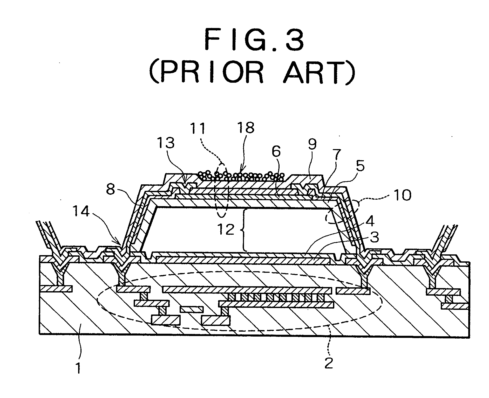
Since the distribution of the fine particles 18 is also not uniform between and within elements, drawbacks occur whereby fluctuations easily occur in the infrared absorption characteristics.
Furthermore, a specialized or dedicated manufacturing apparatus is needed for bonding the fine particles 18, which creates the drawback of increasing the cost of the thermal-type infrared detection element.

Method used


Image

  • Thermal-type infrared detection element
  • Thermal-type infrared detection element
  • Thermal-type infrared detection element

Examples


first embodiment

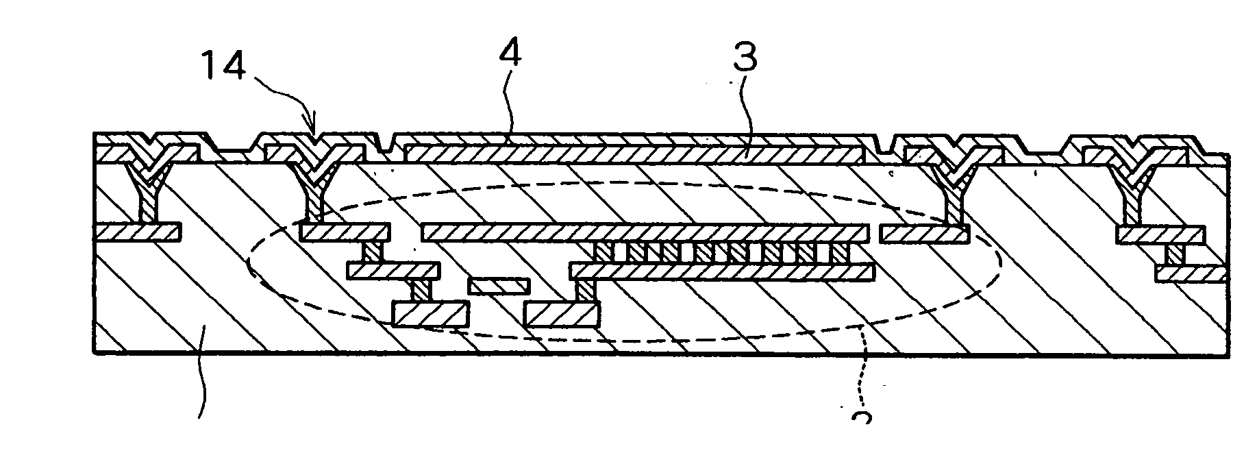
[0035] The thermal-type infrared detection element according to the present invention will first be described with reference to FIGS. 4 through 16. FIG. 4 is a sectional view in which one pixel of the thermal-type infrared detection element of the present embodiment is depicted in alignment with the current path; FIG. 5 is a schematic plane view showing the structure of the convex pattern; and FIG. 6 is a perspective view of the same. FIG. 7 is a sectional view showing variation in the convex pattern; and FIGS. 8 through 15 are sectional views showing the sequence of steps in the method for manufacturing the thermal-type infrared detection element according to the present embodiment. FIG. 16 is a sectional view showing another structure of the thermal-type infrared detection element according to the present embodiment.

[0036] In the thermal-type infrared detection element of the present embodiment as shown in FIG. 4, an infrared reflection film 3 composed of Al, Ti, W, or a silicide ...

second embodiment

[0057] The thermal-type infrared detection element according to the present invention will next be described with reference to FIGS. 17 through 21. FIG. 17 is a sectional view in which one pixel of the thermal-type infrared detection element of the present embodiment is depicted in alignment with the current path; FIG. 18 is a schematic plane view of the structure of the concave pattern; and FIG. 19 is a perspective view thereof. FIG. 20 is a sectional view showing variation in the shape of the concave pattern; and FIG. 21 is a sectional view showing another structure of the thermal-type infrared detection element of the present embodiment.

[0058] The convex pattern 15 was formed on the side of the photoreceptor 11 that is irradiated with infrared rays in the first embodiment described above, but incident infrared rays can be scattered and prevented from reflecting if the surface is not flat, and since the heat capacity of the photoreceptor 11 increases by an amount commensurate with...


PUM


Abstract

A convex pattern in which a plurality of substantially congruent projections composed of an infrared absorbing material are arranged at a substantially constant pitch is formed on the side of a photoreceptor that is irradiated with infrared rays, or a concave pattern in which a plurality of substantially congruent holes are arranged at a substantially constant pitch is formed in an infrared absorption film disposed on the side irradiated with infrared rays, and the infrared rays incident on the photoreceptor are dispersed by the convex pattern or concave pattern. By this configuration, reflection of infrared rays is minimized, the absorption efficiency of infrared rays is increased, and the sensitivity of the thermal-type infrared detection element is enhanced. This convex pattern can be formed using a common semiconductor manufacturing device, and has excellent adhesion to the immediately underlying infrared absorption film. The reliability and uniformity of the thermal-type infrared detection element can therefore be enhanced.

Description

BACKGROUND OF THE INVENTION [0001] 1. Field of the Invention [0002] The present invention relates to a thermal-type infrared detection element, and particularly relates to a structure for an infrared absorption body that constitutes the photoreceptor of a thermal-type infrared detection element. [0003] 2. Description of the Related Art [0004] A thermal-type infrared detection element measures the temperature of an object from the change in resistance that occurs in a heat-sensitive resistor. This usually occurs when infrared rays emitted by a body are absorbed and converted to heat in an infrared absorption body, the temperature of a bolometer thin film or other heat-sensitive resistor that forms a diaphragm having a microbridge structure is increased, and the resistance thereof is changed. [0005] More specifically, this type of thermal-type infrared detection element is composed of a photoreceptor 11 provided with a bolometer layer 6 and an infrared absorption body (infrared absorp...

Claims


Application Information

Patent Timeline
IPC IPC(8): G01N33/00
CPCG01J5/08G01J5/0853G01J5/10G01J5/20
Inventor SASAKI, TOKUHITO
Owner NEC CORP
Learn More