

Inclined magnetic holder
- Summary
- Abstract
- Description
- Claims
- Application Information
AI Technical Summary
Benefits of technology
Problems solved by technology
Method used
Image

Examples
Embodiment Construction
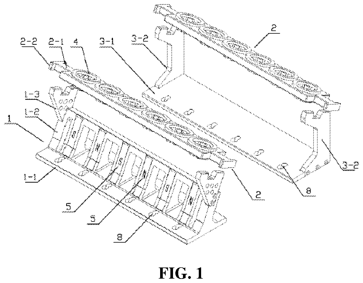
[0052]The present invention is described in detail below with reference to the drawings and specific embodiments. It should be understood that the following detailed description is merely exemplary and illustrative, and should not limit the present invention.
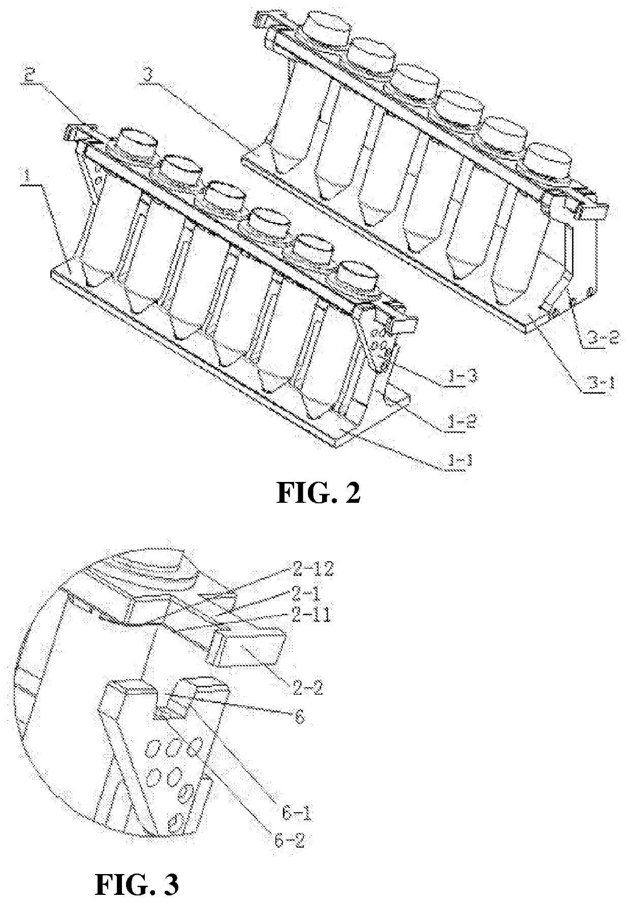
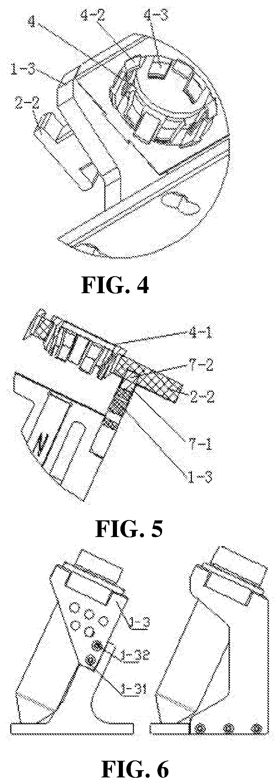
[0053]A structure of an embodiment of an inclined magnetic holder device of the present invention is shown in FIG. 1 to FIG. 9. The inclined magnetic holder device in this embodiment includes a magnetic base 1, a nonmagnetic base 3, and a centrifugal tube supporting plate 2. Centrifugal tube supporting holes are provided on the centrifugal tube supporting plate 2. The centrifugal tube supporting holes are evenly distributed on the centrifugal tube supporting plate 2 in a straight line, that is, the centrifugal tube supporting holes are distributed in a single row. An annular elastic buckle 4 for fixing a centrifugal tube is installed in the centrifugal tube supporting hole. The elastic buckle 4 includes an annular ring 4-1. Lock...
PUM
| Property | Measurement | Unit |
|---|---|---|
| Time | aaaaa | aaaaa |
| Angle | aaaaa | aaaaa |
| Angle | aaaaa | aaaaa |
Abstract
Description
Claims
Application Information