Laminated electrical terminal

a technology of laminated terminals and electrical connections, applied in the direction of coupling contact members, fixed connections, coupling device connections, etc., can solve the problems of difficult alignment of metal layers of laminated terminals, difficulty in stamping and form of thick metal layers, and difficulty in manufacturing connectors, etc., to achieve strong mechanical and good electrical joints

Inactive Publication Date: 2006-08-24
MOLEX INC
View PDF16 Cites 30 Cited by
  • Summary
  • Abstract
  • Description
  • Claims
  • Application Information

AI Technical Summary

Benefits of technology

[0008] In the exemplary embodiment of the invention, a laminated terminal for an electrical connector includes a plurality of flat metal layers juxtaposed to form a laminated structure which includes a joining section, a contact section and a terminating section. A plurality of projections on the joining sections of the layers are interengaged within a respective plurality of recesses in adjacent layers to align the layers and provide a strong mechanical and good electrical joint between the layers.

Problems solved by technology

Laminations increase the strength of the terminal by increasing the thickness thereof, whereas thick metal layers are difficult and expensive to stamp and form of sheet metal of a relatively thick material.
Unfortunately, the plurality of metal layers of laminated terminals are difficult to align during manufacturing processes wherein the layers typically are welded together.
Other problems involve delamination of the layers during fabrication of the terminals, manufacture of the connectors and repeated usage thereof.
The welds have a tendency to break over time and repeated usage.

Method used


Image

  • Laminated electrical terminal
  • Laminated electrical terminal
  • Laminated electrical terminal

Examples


first embodiment

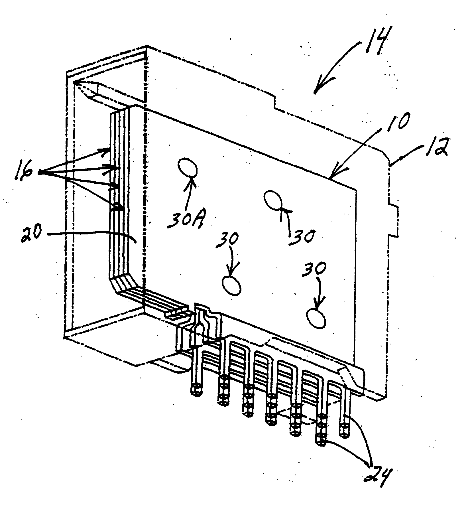
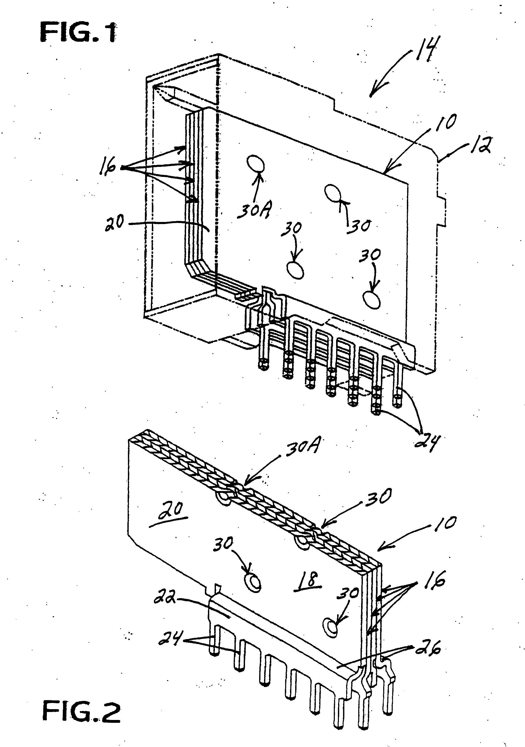
[0031] Referring to the drawings in greater detail, and first to FIG. 1, the invention is incorporated in a laminated terminal structure, generally designated 10, which may be mounted in a dielectric housing 12 of an electrical connector, generally designated 14. In the exemplary embodiment, laminated terminal structure 10 is a “blade terminal” for an electrical power connector. However, it should be understood that the concepts of the invention are equally applicable for a wide variety of different types and configurations of electrical connectors.

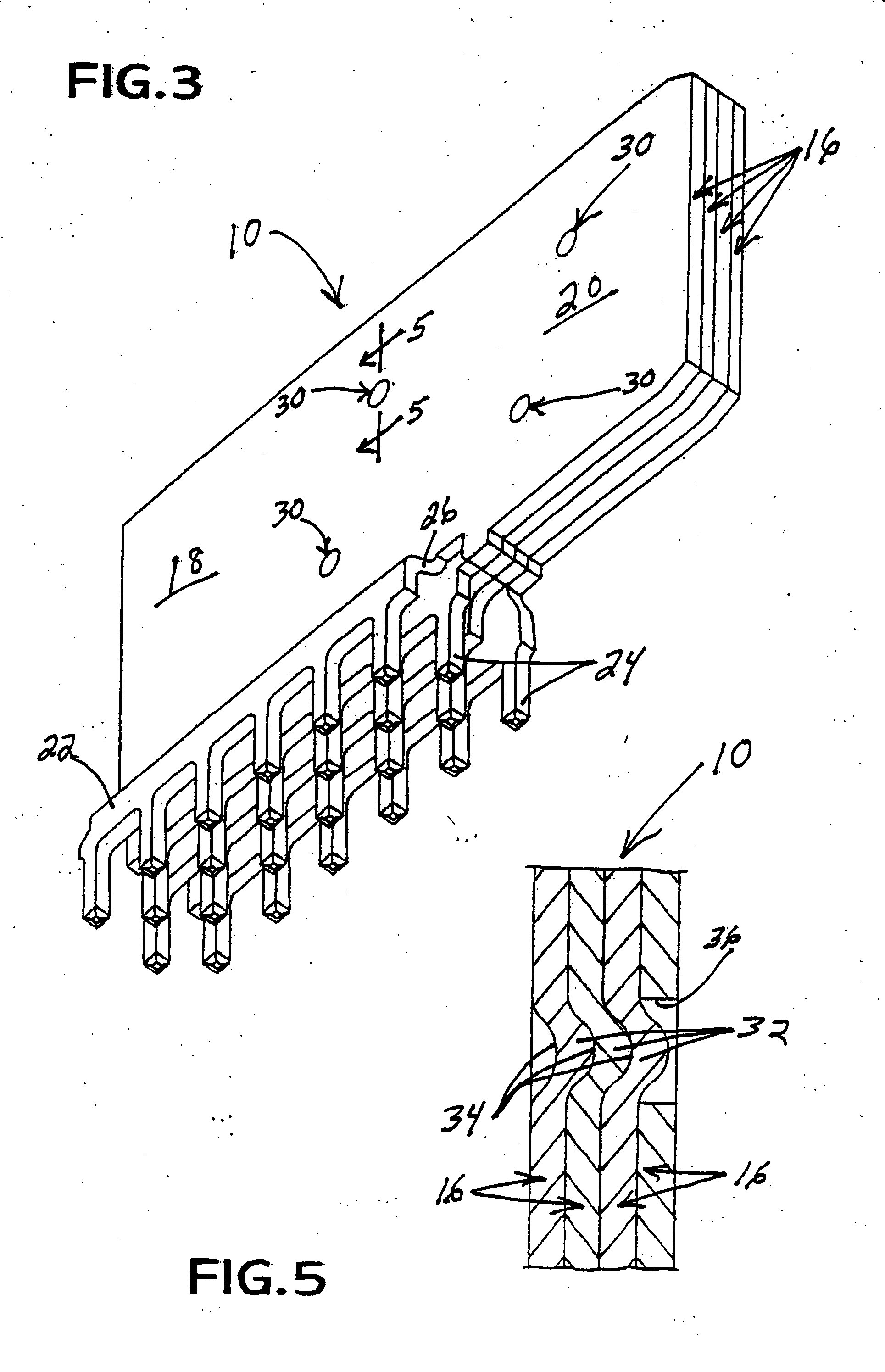
[0032] Referring to FIGS. 2 and 3 in conjunction with FIG. 1, laminated terminal structure 10 is formed of a plurality of flat metal layers, generally designated 16, juxtaposed against each other to form the laminated structure. Each layer includes a joining section 18, a contact section 20 and a terminating section 22. Joining section 18 is a flat plate or body, and contact section 20 is in the form of a blade portion projecting from and...

second embodiment

[0043] FIGS. 8-15 incorporates a unique configuration of the contact blade portions of metal layers 16a and 16b . Generally, the contact blade portion of each metal layer includes at least one generally planar finger which is in a plane parallel and immediately adjacent to a generally planar finger of another of the metal layers. This improves the electrical distribution between the layers and accompanying mating contacts.

[0044] More particularly, each outside metal layer 16b includes a single planar finger 20a which is disposed between and coplanar with a pair of planar fingers 20b of the immediately adjacent inside metal layer 16a . Therefore, the combination of the single planar finger 20a of one of the outside layers 16b and the two planar fingers 20b of the adjacent inside layer 16a forms a single planar blade which has been generally designated 54. There being four metal layers 16a and 16b in laminated structure 10A, it can be seen that two single planar blades 54 are formed b...


PUM


Abstract

A laminated terminal is provided for an electrical connector and includes a plurality of flat metal layers juxtaposed to form a laminated structure. Each metal layer includes a joining section, a contact section and a terminating section. A plurality of projections on the joining sections of the layers are interengaged within a respective plurality of recesses in adjacent layers to align the layers and provide a strong mechanical and good electrical joint between the layers. Solder tails extend linearly along the bottom edge of each joining section to form a plurality of rows of solder tails, and the terminating portions of the metal layers are bent outwardly to separate the rows of solder tails from each other. The contact section of one metal layer may include a generally planar finger which is coplanar with a planar finger of another of the metal layers.

Description

FIELD OF THE INVENTION [0001] This invention generally relates to the art of electrical connectors and, particularly, to a laminated electrical terminal which includes a plurality of juxtaposed metal layers. BACKGROUND OF THE INVENTION [0002] Generally, an electrical connector typically includes some form of insulative or dielectric housing which mounts one or more conductive terminals. The housing is configured for mating with a complementary mating connector or other connecting device which, itself, has one or more conductive terminals. A connector assembly typically includes a pair of mating connectors, such as plug and receptacle connectors sometimes called male and female connectors. The terminals typically have terminating ends exposed at a terminating face of the housing for connection to various conductors, such as discrete conductors of a plurality of electrical cables or the circuit traces on a printed circuit board. The terminals have contact ends located at a mating face...

Claims


Application Information

Patent Timeline
Patent Type & Authority Applications(United States)
IPC IPC(8): H01R13/02H01R12/58
CPCH01R12/724H01R13/03
Inventor BOGIEL, STEVEN B.CARLSON, THOMAS J.HENDRICKSON, WILLIAM P.MCGOWAN, DANIEL B.MILLER, STEVEN D.PATEL, ARVIND
Owner MOLEX INC
Why Eureka
Try Eureka