
Variator and variator arrangement

a variable and variable arrangement technology, applied in the direction of friction gearings, gearing elements, belts/chains/gearings, etc., can solve the problems of large build in the radial direction of the toroidal transmission, unfavorable package, etc., to reduce the transverse movement of the roller, reduce the “stroke” and avoid the flexion of the sha

Active Publication Date: 2006-08-24
GETRAG GETRIEBE & ZAHNRADFABRIK HERMANN HAGENMEYER GMBH & CO KG
View PDF4 Cites 22 Cited by
  • Summary
  • Abstract
  • Description
  • Claims
  • Application Information

AI Technical Summary

Benefits of technology

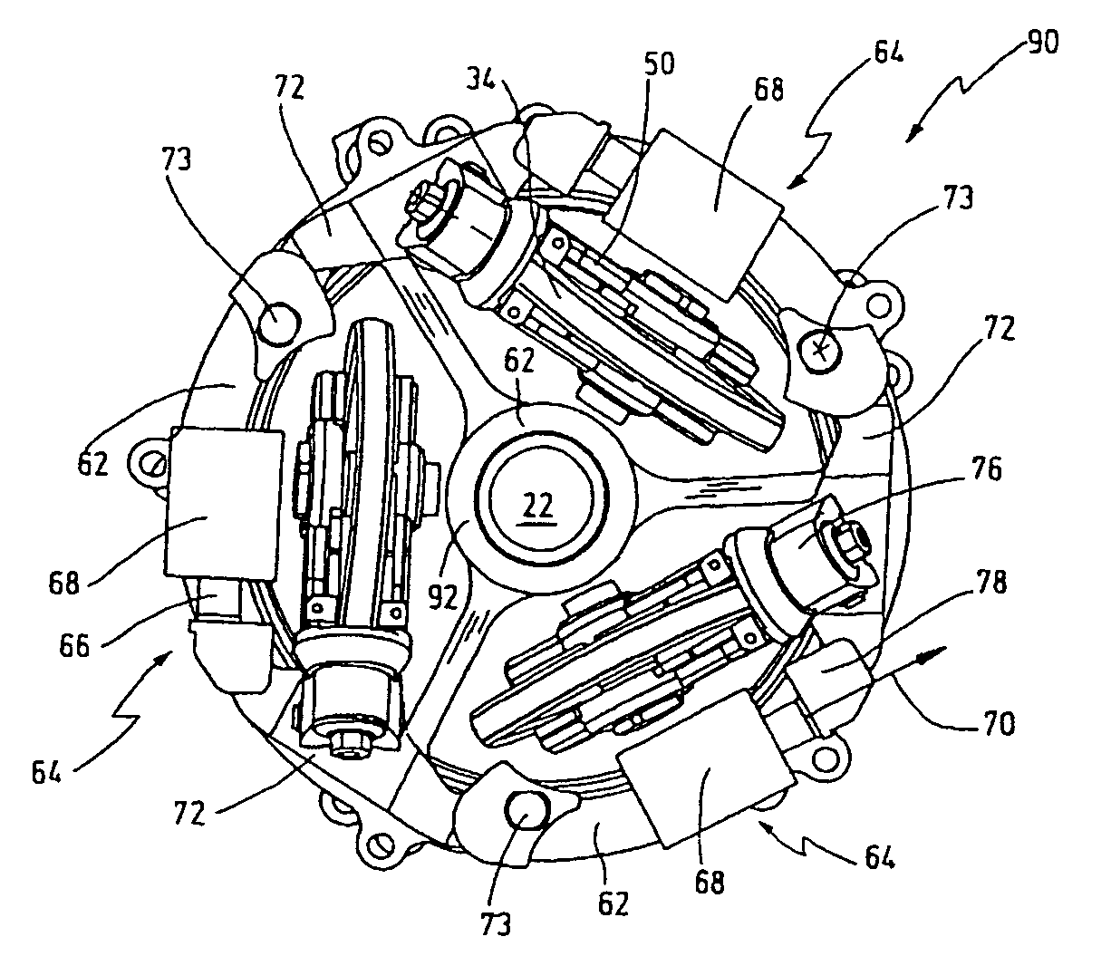
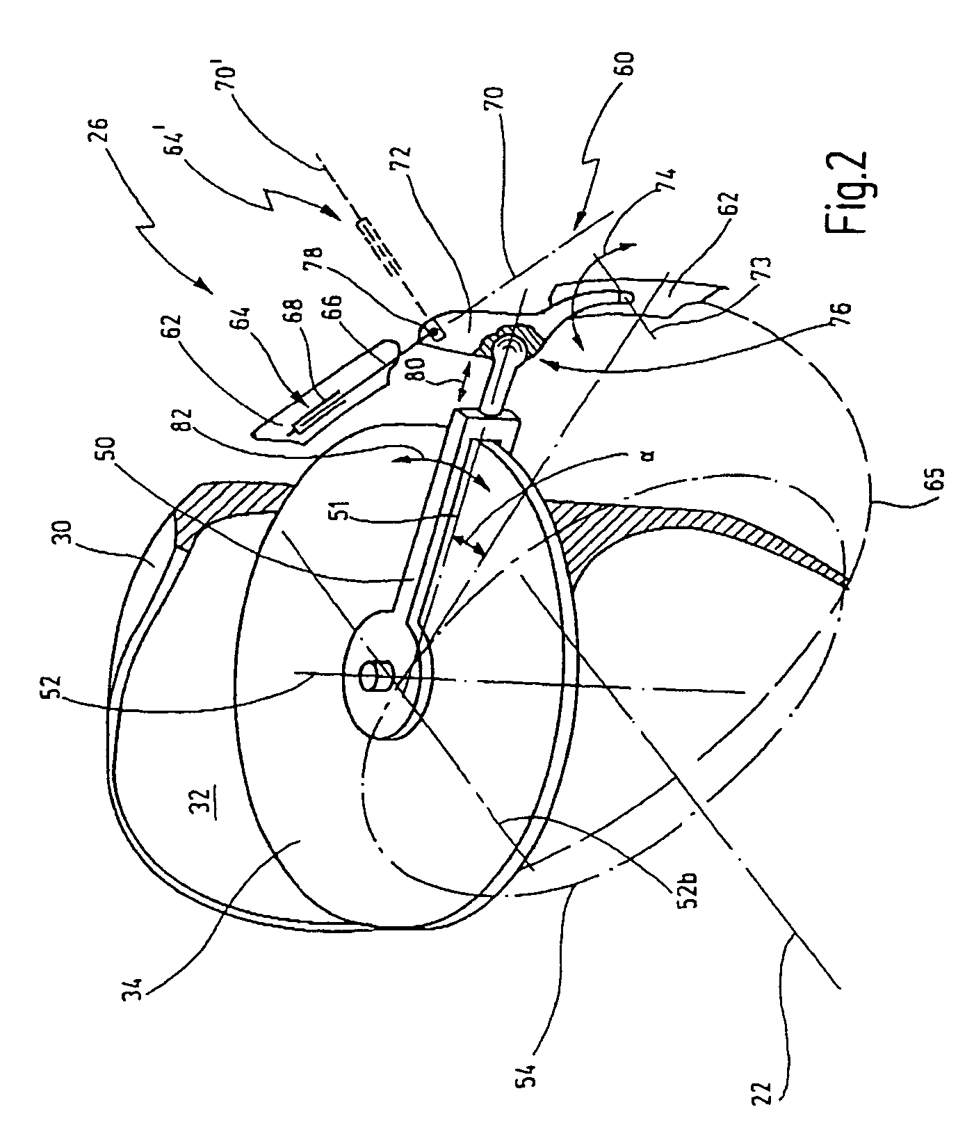
[0013] By virtue of the measure of providing a specific piston / cylinder arrangement for each roller, the cylinder surface of the individual piston / cylinder arrangements can be smaller than in the case of a single piston / cylinder arrangement for all the rollers. Furthermore, by means of the levers, it is possible to arrange the individual piston / cylinder arrangements more favorably, so that the construction space of the variator is reduced especially in the radial direction.
[0056] The variator arrangement, overall, can thereby be constructed as a module, this simplifying mounting into the transmission.

Problems solved by technology

As a result of this arrangement, the cylinders project well beyond the actual contour of the variator, the consequence of this being that the toroidal transmission, overall, has a large build in the radial direction (unfavorable package).

Method used


Image

  • Variator and variator arrangement
  • Variator and variator arrangement
  • Variator and variator arrangement

Examples


Embodiment Construction

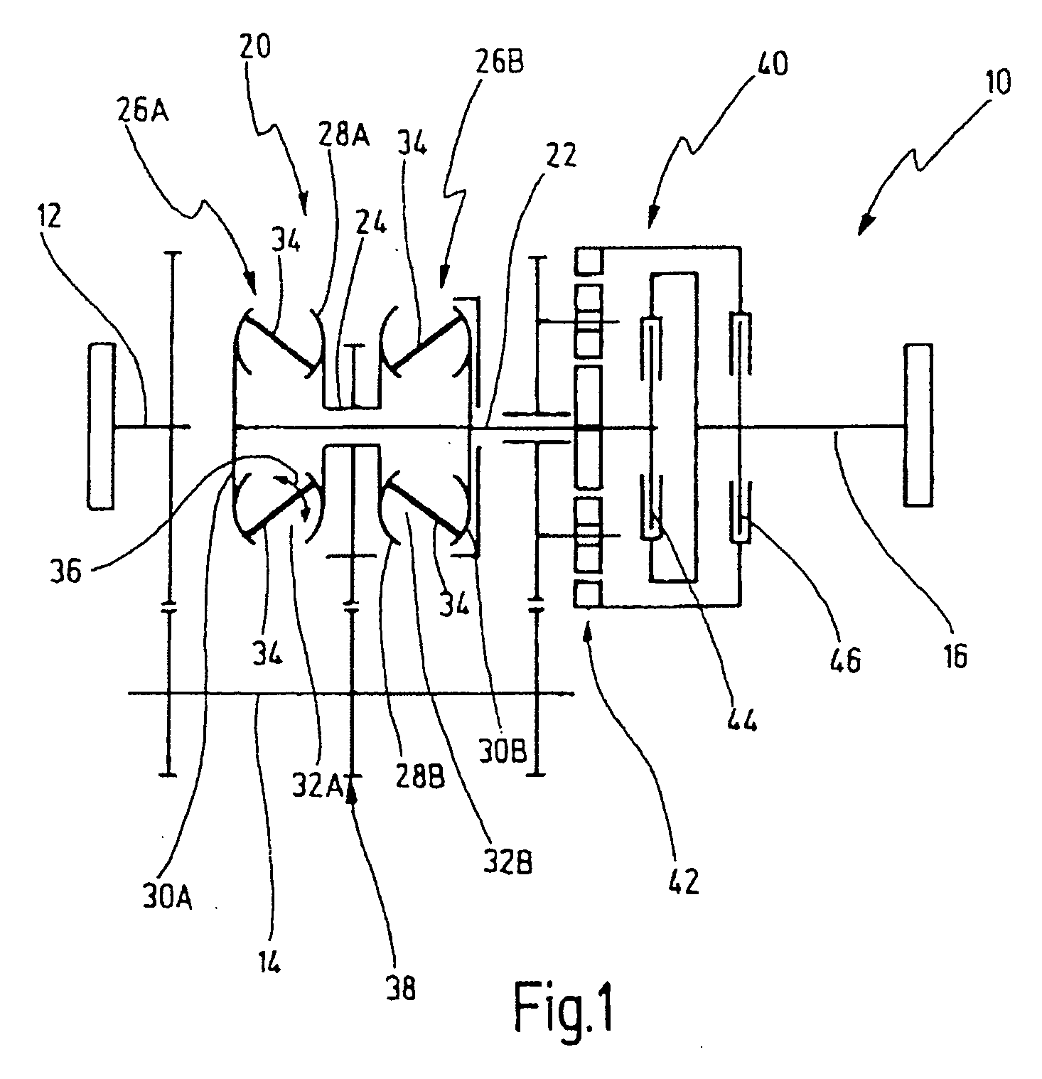
[0063] In FIG. 1, a diagrammatically illustrated toroidal transmission is designated in general by 10.

[0064] The toroidal transmission has a transmission input shaft 12, a countershaft 14 and a transmission output shaft 16.

[0065] A variator arrangement of the toroidal transmission 10 is shown at 20. The variator arrangement 20 has a variator main shaft 22 and a variator secondary shaft 24. The variator arrangement 20 contains, furthermore, two variators 26A, 26B.

[0066] Each variator has a driving disk 28A, 28B and a driven disk 30A, 30B.

[0067] The driving disks 28A, 28B enclose, together with the respective driven disks 30A, 30B, in each case a toroidal space 32A, 32B.

[0068] A plurality of rollers 34, as a rule three rollers 34 in each case, are arranged in each case in the toroidal spaces 32A, 32B so as to be distributed circumferentially over the toroidal space.

[0069] The rollers 34 can be adjusted spatially within the toroidal space 32 by means of an actuator mechanism, not...


PUM


Abstract

A variator for a toroidal transmission, with a driving disk and with a driven disk, between which is set up a toroidal space which defines a toroidal reference circle. The variator, further, comprises at least two rollers which are arranged in the toroidal space for torque transfer between the driving disk and the driven disk. The rollers are in each case mounted rotatably on a roller carrier. The roller carriers are in each case spatially adjustable by means of a piston / cylinder arrangement, in order to adjust the transfer ratio of the variator. The pistons of the piston / cylinder arrangements are in each case adjustable along a stroke axis. Also, the pistons are connected to the roller carriers via respective levers.

Description

CROSS REFERENCE TO RELATED APPLICATIONS [0001] This application is a continuation of International Application PCT / EP2004 / 008669, filed on Aug. 3, 2004. This application is hereby incorporated by reference in its entirety. BACKGROUND OF THE INVENTION [0002] 1. Field of the Invention [0003] The present invention relates to a variator for a toroidal transmission, with a driving disk and with a driven disk, between which is set up a toroidal space which defines a toroidal reference circle, and with at least two rollers which are arranged in the toroidal space for torque transfer between the driving disk and the driven disk, the rollers being in each case mounted rotatably on a roller carrier, the roller carriers being in each case spatially adjustable by means of a piston / cylinder arrangement, in order to adjust the transfer ratio of the variator, and the pistons of the piston / cylinder arrangements being in each case adjustable along a stroke axis. [0004] The present invention relates,...

Claims


Application Information

Patent Timeline
IPC IPC(8): F16H15/38
CPCF16H15/38
Inventor FLAIG, ARMINRUEHLE, GUENTHER
Owner GETRAG GETRIEBE & ZAHNRADFABRIK HERMANN HAGENMEYER GMBH & CO KG
Learn More