
Security for logical unit in storage subsystem

Inactive Publication Date: 2006-08-24
HITACHI LTD
View PDF90 Cites 21 Cited by
  • Summary
  • Abstract
  • Description
  • Claims
  • Application Information

AI Technical Summary

Benefits of technology

[0018] In this storage subsystem, a user can make setting of accessible LUN and setting on a connection interface in an arbitrary group unit of computers under a single port without changing existing processing, limitation and other functions of the computers. Therefore, this storage subsystem can accomplish an access control function, that is, a LUN security function, for computer groups having a plurality of kinds of OS under a single port.

Problems solved by technology

Under such circumstances, the security function to the storage subsystem resources that relies on OS, middleware and application software on the host side according to the prior art technology is not sufficient in some cases, and the necessity for a higher LUN security function for preventing an illegal access to logical units (hereinafter abbreviated as “LU” from time to time) has increased rapidly.
The method of this reference accomplishes the security function as to access approval / rejection to LUN inside the storage subsystem but cannot cope with diversified computers that gain access to a single port.
In the practical operation, therefore, the method limits the kind of host computers that can be managed under the single port to only one kind.
This limitation in the practical operation cannot follow drastic expansion of the SAN environment described above.
Nonetheless, the LUN security function in the existing storage subsystems is not free from the limitation that the kind of OS must be the same even when a large number of computers that can be managed under the single port exist.
Furthermore, such a function generally has another limitation that setting of connection interface for the host computers that can be set to the single port must be one.
Therefore, when the logical unit number (LUN) inside the storage subsystem is as such given to the host computer, the computer cannot correctly recognize the logical unit as expected on the setting side of the logical units.
In other words, even when 257 or more of logical unit number are disposed, the computers cannot recognize the logical units, and this also renders the problem when the logical units inside the storage subsystem are given to the computer under the single port.
However, this creates the problem of performance because the processing time in the storage subsystem (overhead for security check) becomes greater.

Method used


Image

  • Security for logical unit in storage subsystem
  • Security for logical unit in storage subsystem
  • Security for logical unit in storage subsystem

Examples


Embodiment Construction

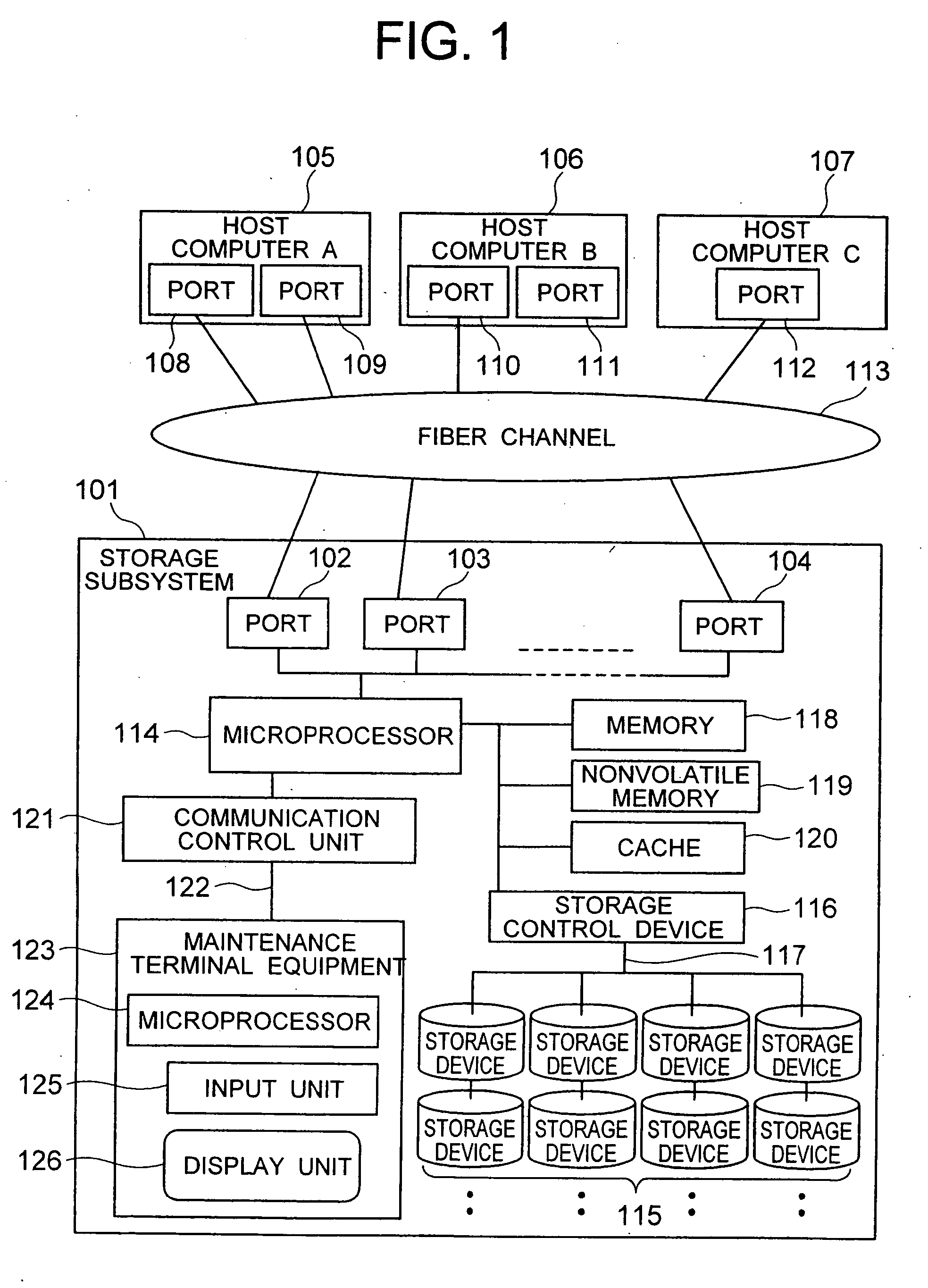
[0040] The present invention utilizes by way of example a Fiber Channel as an example of an interface protocol used between a storage subsystem and a computer and an SCSI command as an example of a command set operating on the interface protocol. Incidentally, the invention is not limited to the combination of the Fiber Channel and the SCSI command but can be applied to any combination of protocols and interfaces so long as they can provide the functions / mechanisms of login, inquiry, logout, and so forth.

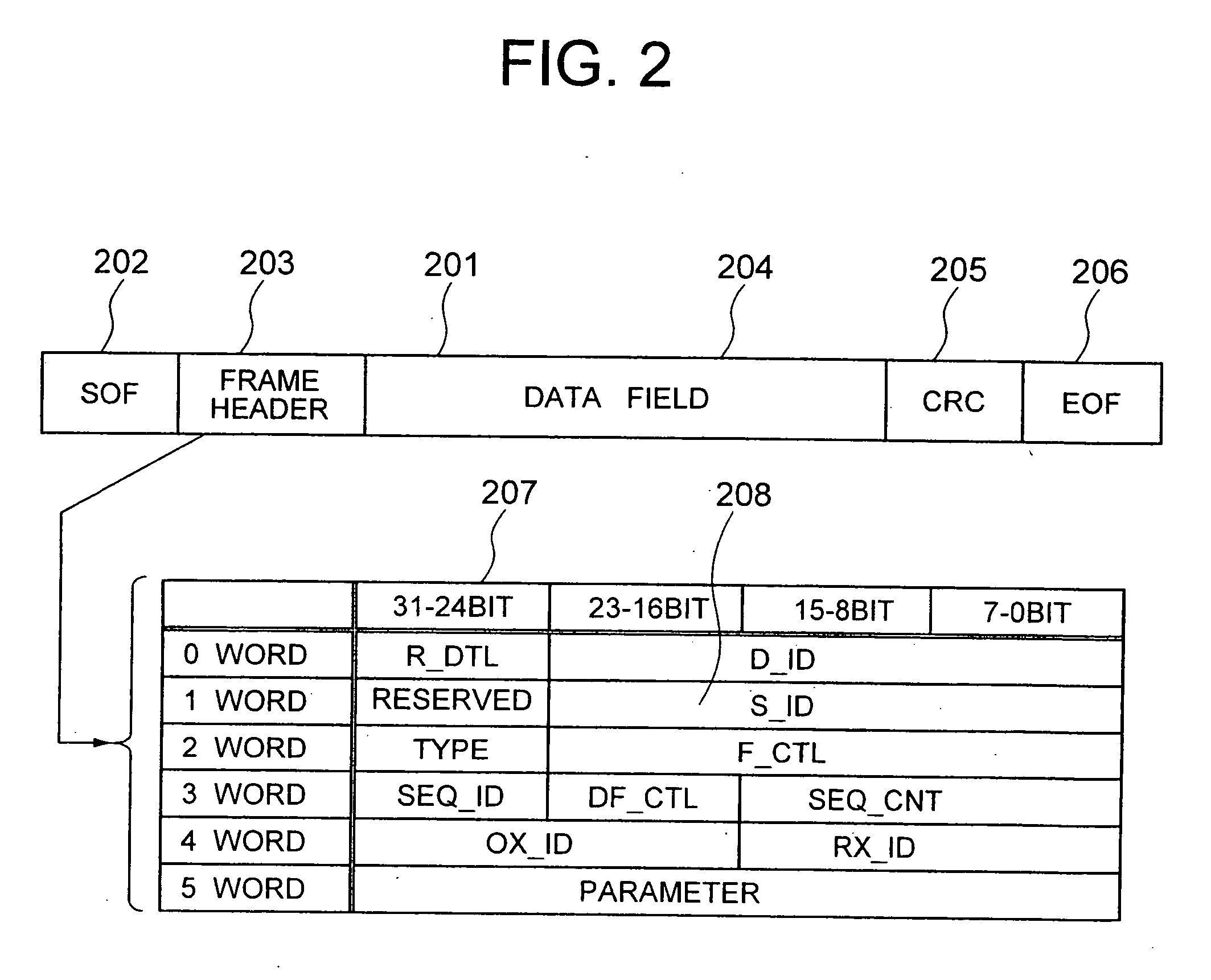
[0041] A first embodiment of the invention will be given. Initially, the features associated with the invention on the protocol of the Fiber Channel will be explained.

[0042] A device having an interface of the Fiber Channel is referred to as a “node”, and a physical terminal corresponding to a practical interface is referred to as a “port”. The node can have one or more ports. The number of ports that can simultaneously participate in the overall system of the Fiber Channel is the...


PUM


Abstract

Mapping tables are for stipulating information for primarily identifying computers, information for identifying a group of the computers and a logical unit number permitting access from the host computer inside storage subsystem, in accordance with arbitrary operation method by a user, and for giving them to host computer. The invention uses management table inside the storage subsystem and allocates logical units inside the storage subsystem to a host computer group arbitrarily grouped by a user in accordance with the desired form of operation of the user, can decide access approval / rejection to the logical unit inside the storage subsystem in the group unit and at the same time, can provide the security function capable of setting interface of connection in the group unit under single port of storage subsystem without changing existing processing, limitation and other functions of computer.

Description

[0001] The present application is a Continuation of application Ser. No. 10 / 902,795, filed Aug. 2, 2004; which is a continuation of application Ser. No. 10 / 076,553, filed Feb. 19, 2002, now U.S. Pat. No. 6,779,083 and claims priority from Japanese Patent Application No. 2001-213642; and is a Continuation-in-part of application Ser. No. 11 / 330,261, filed Jan. 12, 2006; which is a continuation of application Ser. No. 10 / 737,477, filed Dec. 15, 2003, now U.S. Pat. No. 7,024,410; which is a continuation of application Ser. No. 09 / 561,404, filed Apr. 27, 2000, now U.S. Pat. No. 6,684,209 and claims priority from Japanese Patent Application Reference No. 2000-010115, filed Jan. 14, 2000 the entire disclosures of each of the above are incorporated herein by reference.BACKGROUND OF THE INVENTION [0002] 1. Filed of the Invention [0003] This invention relates to a storage subsystem to be accessed from a computer. More particularly, this invention relates to an access to a logical unit inside ...

Claims


Application Information

Patent Timeline
IPC IPC(8): G06F12/00
CPCG06F3/0622G06F3/0637G06F3/067G06F21/805H04L63/10H04L63/20H04L67/1097
Inventor ITO, RYUSKEOKAMI, YOSHINORIUCHIUMI, KATSUHIROIGARASHI, YOSHINORIHORI, KOICHI
Owner HITACHI LTD
Learn More