Fluid filter apparatus for vehicle and manufacturing method thereof

a technology vehicle, which is applied in the direction of filtration separation, separation process, application, etc., can solve the problems of increasing the cost of facilities and increasing the cost of fluid filtering apparatus, and achieve the effect of preventing welding failure of filter elements and low transmittance for laser ligh

Inactive Publication Date: 2006-08-31
DAIKYONISHIKAWA CORP
View PDF5 Cites 19 Cited by
  • Summary
  • Abstract
  • Description
  • Claims
  • Application Information

AI Technical Summary

Benefits of technology

[0016] In the above constitution, the traveling speed of the laser light for irradiation in welding the peripheral part of the filter element is set lower than the traveling speed of the laser light for irradiation in welding the contact faces of the flange portions to each other. This allows a sufficient amount of the laser light to pass through the peripheral part of the filter element, which has comparatively low transmittance for laser light, attaining reliable melting of the inner face located inside the flange portion of the other casing. Further, when the output level of the laser light for irradiation in welding the peripheral part of the filter element is set larger than the output level of the laser light for irradiation in welding the contact faces of the flange portions, reliable melting of the inner face located inside of the flange portion can be attained, as well. As a result, welding failure of the filter element can be prevented.

Problems solved by technology

In this connection, a large-scale and high-output laser light emitter is required, which increases the cost of facilities, and in turn, increases the cost of the fluid filtering apparatus.

Method used


Image

  • Fluid filter apparatus for vehicle and manufacturing method thereof
  • Fluid filter apparatus for vehicle and manufacturing method thereof
  • Fluid filter apparatus for vehicle and manufacturing method thereof

Examples


Embodiment Construction

[0021] An embodiment of the present invention will be described below with reference to the accompanying drawings. Wherein, the following description of the preferred embodiment is substantially a mere example and is not intended to limit the present invention, object to which it is applied, and the use thereof.

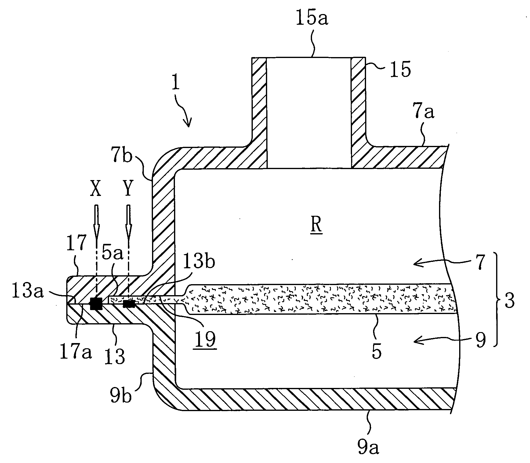
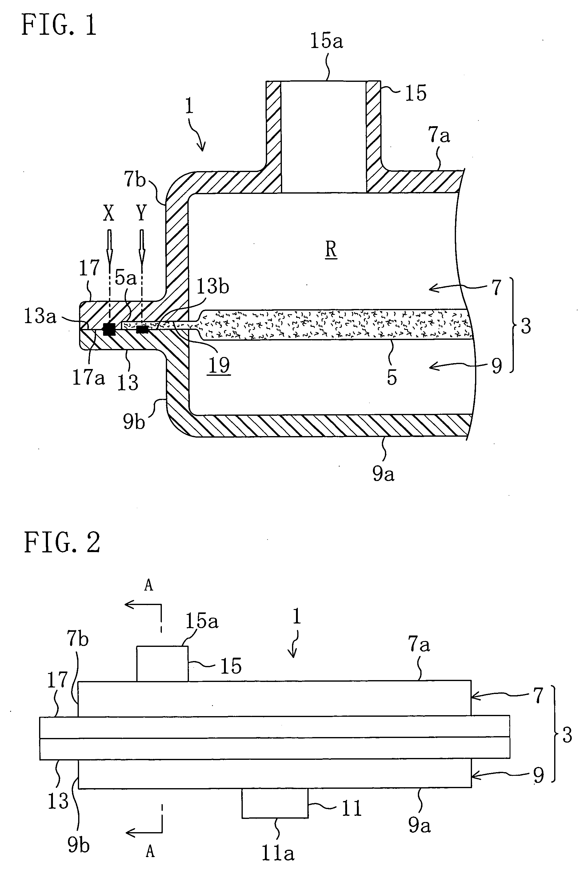
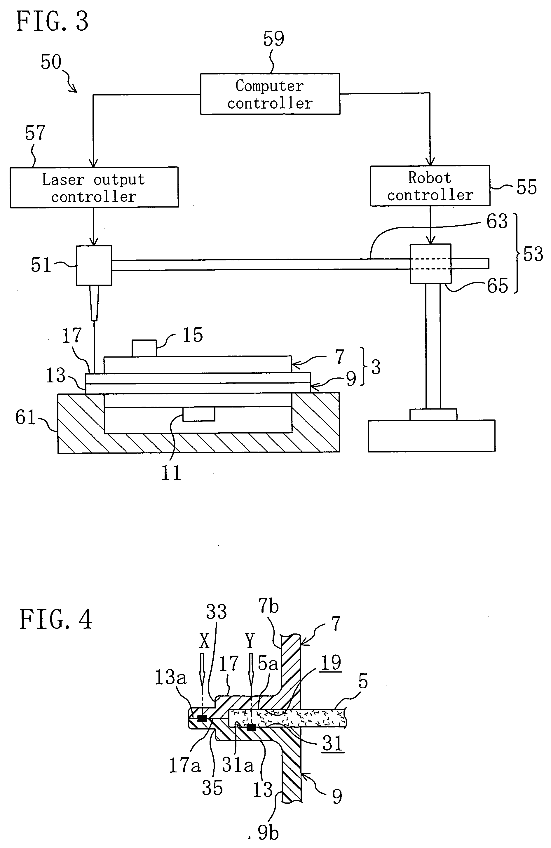
[0022]FIG. 1 shows a fluid filtering apparatus 1 for a vehicle according to an embodiment of the present invention. The fluid filtering apparatus 1 is provided at an automatic transmission (not shown) of an automobile for filtering oil circulating within the automatic transmission.

[0023] The fluid filtering apparatus 1 includes a resin-made casing 3 substantially in a rectangular shape and a filter element 5 arranged in an inner space R of the casing 3 for filtering oil. The casing 3 is divided at substantially the central part into upper and lower two parts, as shown in FIG. 2, namely, is composed of an assembly of an upper half casing member 7 and a lower half casing memb...


PUM

PropertyMeasurementUnit
transmittanceaaaaaaaaaa
traveling speedaaaaaaaaaa
energyaaaaaaaaaa

Abstract

An upper half casing member is made of a resin capable of transmitting laser light while a lower half casing member is made of a resin incapable of transmitting laser light. An upper flange portion and a lower flange portion are formed at the respective casing members so as to protrude outwards of a casing from respective peripheral walls thereof. A housing concave part and an upper contact face are formed in the lower face portion of the upper flange portion. A lower contact face is formed in the upper face of the lower flange portion. Laser light is irradiated to the lower flange portion through the upper flange portion to weld the contact faces to each other and to weld an element welding face at the upper face of the lower flange portion to a peripheral part of a filter element.

Description

CROSS REFERENCE TO RELATED APPLICATIONS [0001] This Non-provisional application claims priority under 35 U.S.C. § 119(a) on Patent Application No. 2005-053884 filed in Japan on Feb. 28, 2005, the entire contents of which are hereby incorporated by reference. BACKGROUND ART [0002] The present invention relates to a fluid filtering apparatus for a vehicle which is used for filtering oil circulating within an automatic transmission of an automobile, for example, and a method for manufacturing it. [0003] As disclosed in Japanese Patent Application Laid Open Publication No. 2004-148592A, for example, a conventional fluid filtering apparatus for a vehicle has been known which includes a resin-made casing and a filter element disposed within the casing for filtering oil. This casing of the fluid filtering apparatus is composed of an assembly of a first half casing member and a second half casing member. The first half casing member includes a end wall in which an oil inlet is formed and a ...

Claims


Application Information

Patent Timeline
Patent Type & Authority Applications(United States)
IPC IPC(8): B01D35/28B29C65/16F16B5/08F16H57/02F16H57/04
CPCB01D27/005B01D46/0001F16H57/0404F02M37/22B29L2031/14B29L2022/00B29K2105/0854B29K2067/00B01D2265/04B01D2271/025B29C65/1635B29C65/1654B29C65/7841B29C66/1312B29C66/232B29C66/3452B29C66/5412B29C66/863B01D27/07B01D27/08B29C65/00B29C66/934B29C66/73921B29C66/71B29C66/712B29C66/652B29K2077/00
Inventor HOMI, NOBUYUKI
Owner DAIKYONISHIKAWA CORP
Why Eureka
Try Eureka