
Microwave heating system

a heating system and microwave technology, applied in the direction of electric/magnetic/electromagnetic heating, coupling device connection, coupling parts engagement/disengagement, etc., can solve the problems of cross-talk between separate channels, structural complexity of e.g. moderating means, etc., and achieve the effect of low cos

Inactive Publication Date: 2006-08-31
BIOTAGE INC
View PDF4 Cites 54 Cited by
  • Summary
  • Abstract
  • Description
  • Claims
  • Application Information

AI Technical Summary

Benefits of technology

[0015] The goal of this system is to simultaneously heat as many chemical reactions as possible in the shortest period of time to the lowest cost per sample as possible.
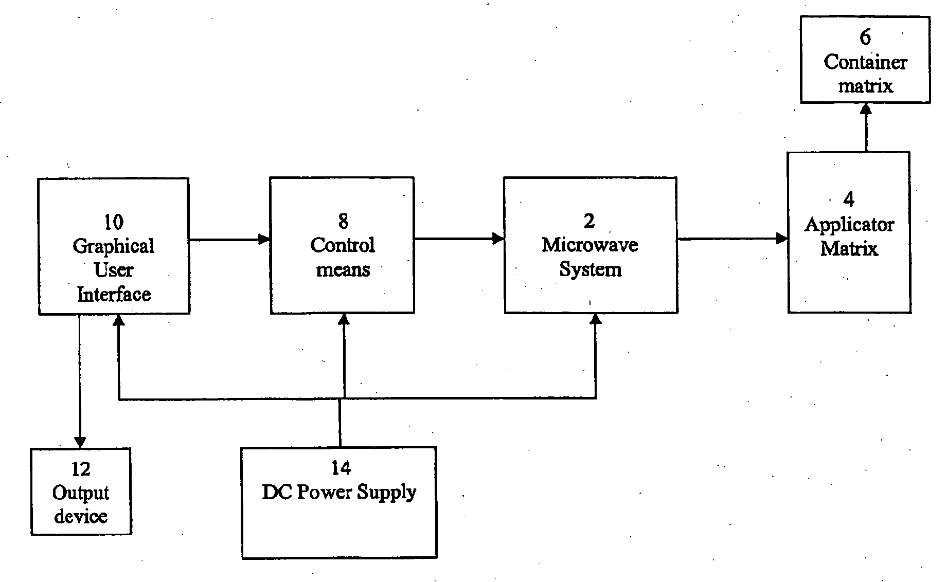
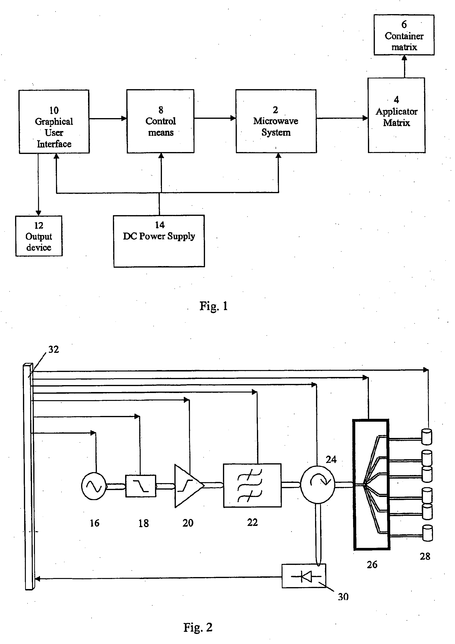
[0016] A number of advantages of the microwave heating system according to the present invention are that the whole system will require only one power amplifier and only one microwave signal generator, and there is minimum risk of mutual coupling between the applicators due to the possibility to freely dedicate a specific applicator to a specific time slot.
[0017] A great benefit of a computer-controlled microwave heating system is that it can steer all individual chemical reactions independently in power, frequency and time, and it can be programmed to learn from the results of the chemical reactions in order to modify heating profiles.

Problems solved by technology

It is considered that one drawback with this known device is the structural complexity of e.g. the moderating means and cross-talk between the separate channels.

Method used


Image

  • Microwave heating system
  • Microwave heating system
  • Microwave heating system

Examples


Embodiment Construction

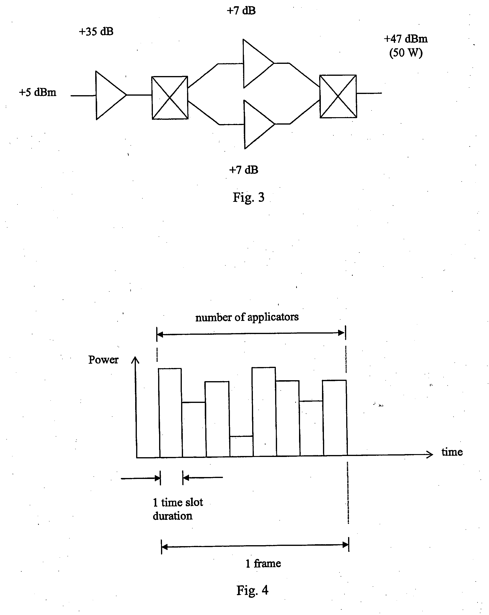
[0026] Initially a bit more should be said here about the nature of microwave heating. Maximum power is generally only required for a small percentage of the total processing time. Another percentage of the time it will require no power at all.

[0027] As mentioned above, the goal of the present invention is to achieve a system adapted to heat as many individual chemical reactions as possible in the shortest period of time to the lowest cost per sample as possible. There will naturally be a compromise between total process time, number of reactions and power available for heating.

[0028] System equations and heating profiles will determine the maximum dedicated slot time a reaction may be allowed in order for the chemical reaction to be maintained. This will naturally be dependent on the rate of microwave absorption of the chemistry and heating profile parameters can be changed at any time.

[0029] In order to design the system hardware it will be necessary to determine how many power...


PUM


Abstract

Microwave heating system comprising a plurality of microwave applicators for heating loads arranged in said applicators, a control means, one microwave generator to generate microwave energy having a controllable frequency and power level, and a microwave switch arranged to connect said microwave generator to each of said applicators. Each microwave applicator is dedicated a heating time slot in a time frame, and that said time frame comprises time slots for applicators to be heated. During microwave heating, microwave energy is applied to the microwave applicators in its respective time slot, in consecutive time frames.

Description

FIELD OF THE INVENTION [0001] The present invention relates to a microwave heating system and a method in a microwave heating system according to the preambles of the independent claims. BACKGROUND OF THE INVENTION [0002] A microwave heating system for carrying out chemical reactions, and particularly organic synthesis reactions, is an important and well-known technique. Using microwave heating in a very special way makes it possible to increase the reaction rate of chemical reactions by orders of magnitude. The use of microwaves also often leads to higher yield and purity of the final product. [0003] Microwave assisted chemistry has been used for many years. However, the apparatuses and methods have to a great extent been based upon conventional domestic microwave ovens. Domestic microwave ovens have a multimode cavity and the energy is applied at a fixed frequency at 2450 MHz. The use of single mode cavities have also been reported, see e.g. U.S. Pat. No. 5,393,492 and U.S. Pat. N...

Claims


Application Information

Patent Timeline
Patent Type & Authority Applications(United States)
IPC IPC(8): H05B6/64B01J19/12H05B6/68
CPCB01J19/126B01J2219/1218B01J2219/1275B01J2219/1281H05B6/666H05B6/686H05B6/70H05B6/705H05B6/806
Inventor RAY, IAN CHRISTOPHERFAGRELL, MAGNUS
Owner BIOTAGE INC
Learn More