Manufacturing methods for embedded optical system

a manufacturing method and optical system technology, applied in the field of manufacturing methods for embedded optical systems, can solve the problems of optical distortion, difficult actual manufacturing of embedded optical systems, and change the relative positions of embedded components

Inactive Publication Date: 2006-08-31
GOOGLE LLC
View PDF29 Cites 122 Cited by
  • Summary
  • Abstract
  • Description
  • Claims
  • Application Information

AI Technical Summary

Problems solved by technology

In practice, the actual manufacturing of embedded optical systems may be quite difficult.
This can cause optical distortion and change the relative positions of the embedded components.
This may result in birefringence in the completed part.
This material has 13-16% shrinkage upon curing, making it challenging to use for embedded systems.
The other commercially available polymers for lens casting have shrinkage at least 6% that is also excessive for the fabrication of embedded systems.
The pre-polymerization process is not easy to control and polymerization does no...

Method used


Image

  • Manufacturing methods for embedded optical system
  • Manufacturing methods for embedded optical system
  • Manufacturing methods for embedded optical system

Examples


Embodiment Construction

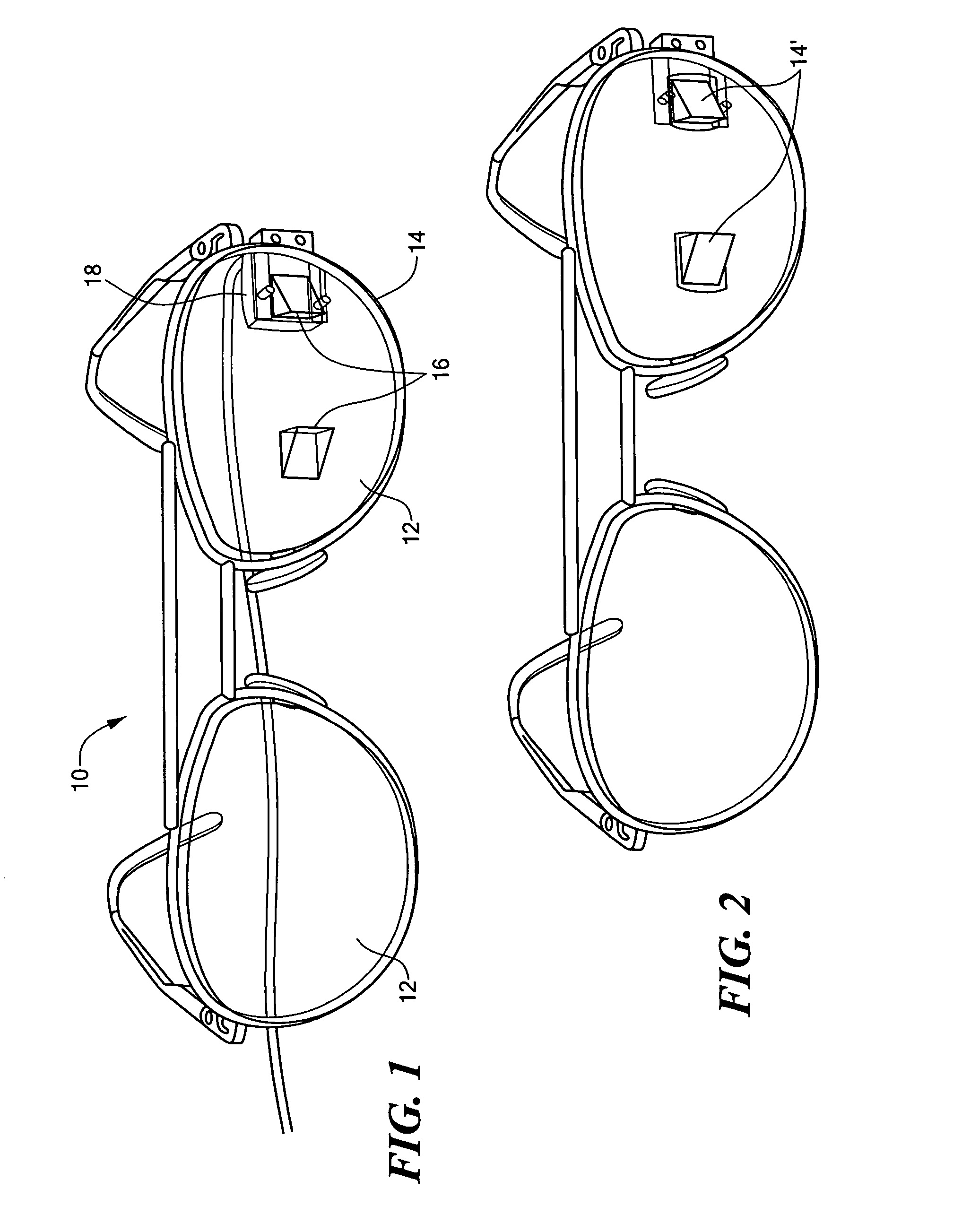
[0028]FIG. 1 illustrates a pair of eyeglasses 10 having two eyeglass lenses 12 retained within an eyeglass frame 14. In one lens, optical elements or components 16 are embedded to receive an image from a display 18 and transmit the image to the wearer's eye. FIG. 1 illustrates a see-through system, in which the wearer can also view the ambient scene through the optical elements. FIG. 2 is similar to FIG. 1, but illustrates a see-around system in which the embedded optical elements 14′ block a portion of the light from the ambient scene and the ambient scene is viewed around the optical elements. The optical elements, which may be, for example, lenses, mirrors, beam splitters and polarizers, are formed separately in any manner known in the art. The elements are then embedded in the lens as described further below.

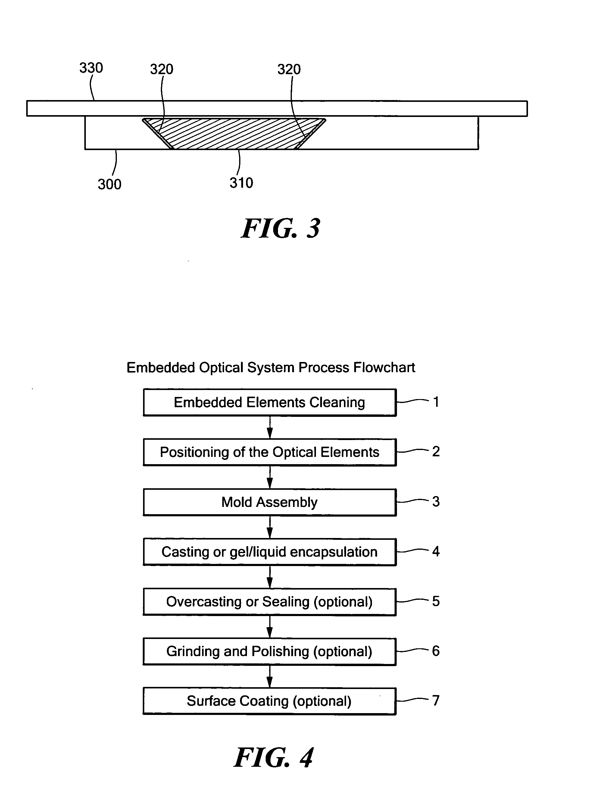
[0029] To avoid contamination on the embedded optical parts it may be necessary to clean the optical elements to be embedded prior to the embedding process. See step 1 in F...


PUM

PropertyMeasurementUnit
Shrinkageaaaaaaaaaa
Shrinkageaaaaaaaaaa
Shrinkageaaaaaaaaaa

Abstract

A method for producing a solid optical system with embedded elements is provided. The embedded elements may include inorganic, polymer, or hybrid lenses, mirrors, beam splitters and polarizers, or other elements. The embedding material is a transparent high quality optical polymer.

Description

CROSS REFERENCE TO RELATED APPLICATIONS [0001] N / A STATEMENT REGARDING FEDERALLY SPONSORED RESEARCH OR DEVELOPMENT [0002] N / A BACKGROUND OF THE INVENTION [0003] Fabricating optical systems such as head mounted displays often requires assembling several optical components. See for example U.S. Pat. Nos. 6,538,624; 6,462,882; 6,147,807. Some optical system designs include an air gap between the optical components. This creates the necessity for a housing to hold the elements in mechanical alignment as well as a method of protecting the inner surfaces of the components from dust, oil and other contamination. Other optical systems allow the gap to be filled by some other medium. These systems can be built, for example, by embedding reflective, diffractive, polarizing or other optical components into an optically transparent solid medium. See for example U.S. Pat. Nos. 5,886,882, 6,091,546, and 6,384,922. An advantage of this approach is that the resulting system is a monolithic solid pa...

Claims


Application Information

Patent Timeline
IPC IPC(8): B29D11/00
CPCB29C39/006B29C39/405B29C39/42B29C43/18B29D11/00009B29K2709/08B29D11/00
Inventor GILLER, EUGENERENSING, NOA M.ZAVRACKY, PAUL M.
Owner GOOGLE LLC
Why Eureka
Try Eureka