
Power line communications device and method

a power line and communication device technology, applied in the field of data communication, can solve the problems of many challenges to overcome, power lines are not designed to provide high-speed data communication, and are susceptible to interferen

Inactive Publication Date: 2006-08-31
CURRENT TECH
View PDF99 Cites 337 Cited by
  • Summary
  • Abstract
  • Description
  • Claims
  • Application Information

AI Technical Summary

Benefits of technology

Enables reliable and efficient data communication over power lines, overcoming signal loss and interference issues, and meeting regulatory power limits, by using amplifiers and fiber optic converters to support multiple users and transformer connections.

Problems solved by technology

While the concept may sound simple, there are many challenges to overcome in order to use power lines for data communication.
Power lines are not designed to provide high speed data communications, are susceptible to interference, and are very lossy at the frequencies used for data communications.
Additionally, federal regulations limit the amount of radiated energy of a power line communication system, which therefore limits the power of the data signal that can be injected onto power lines.
Power system transformers are one obstacle to using power distribution lines for data communication.
As such, power line communication systems face the challenge of communicating the data signals around, or through, the distribution transformers.

Method used


Image

  • Power line communications device and method
  • Power line communications device and method
  • Power line communications device and method

Examples


Embodiment Construction

[0025] In the following description, for purposes of explanation and not limitation, specific details are set forth, such as particular networks, communication systems, computers, terminals, devices, components, techniques, data and network protocols, software products and systems, operating systems, development interfaces, hardware, etc. in order to provide a thorough understanding of the present invention.

[0026] However, it will be apparent to one skilled in the art that the present invention may be practiced in other embodiments that depart from these specific details. Detailed descriptions of well-known networks, communication systems, computers, terminals, devices, components, techniques, data and network protocols, software products and systems, operating systems, development interfaces, and hardware are omitted so as not to obscure the description of the present invention.

System Architecture and General Design Concepts

[0027] Power distribution systems typically include co...


PUM


Abstract

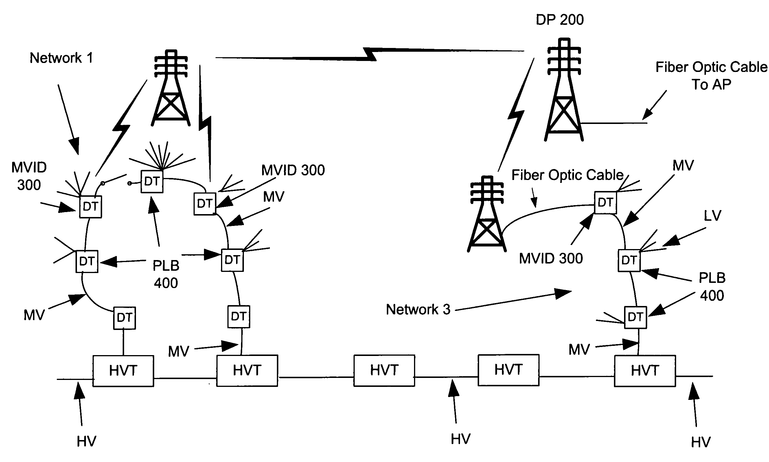
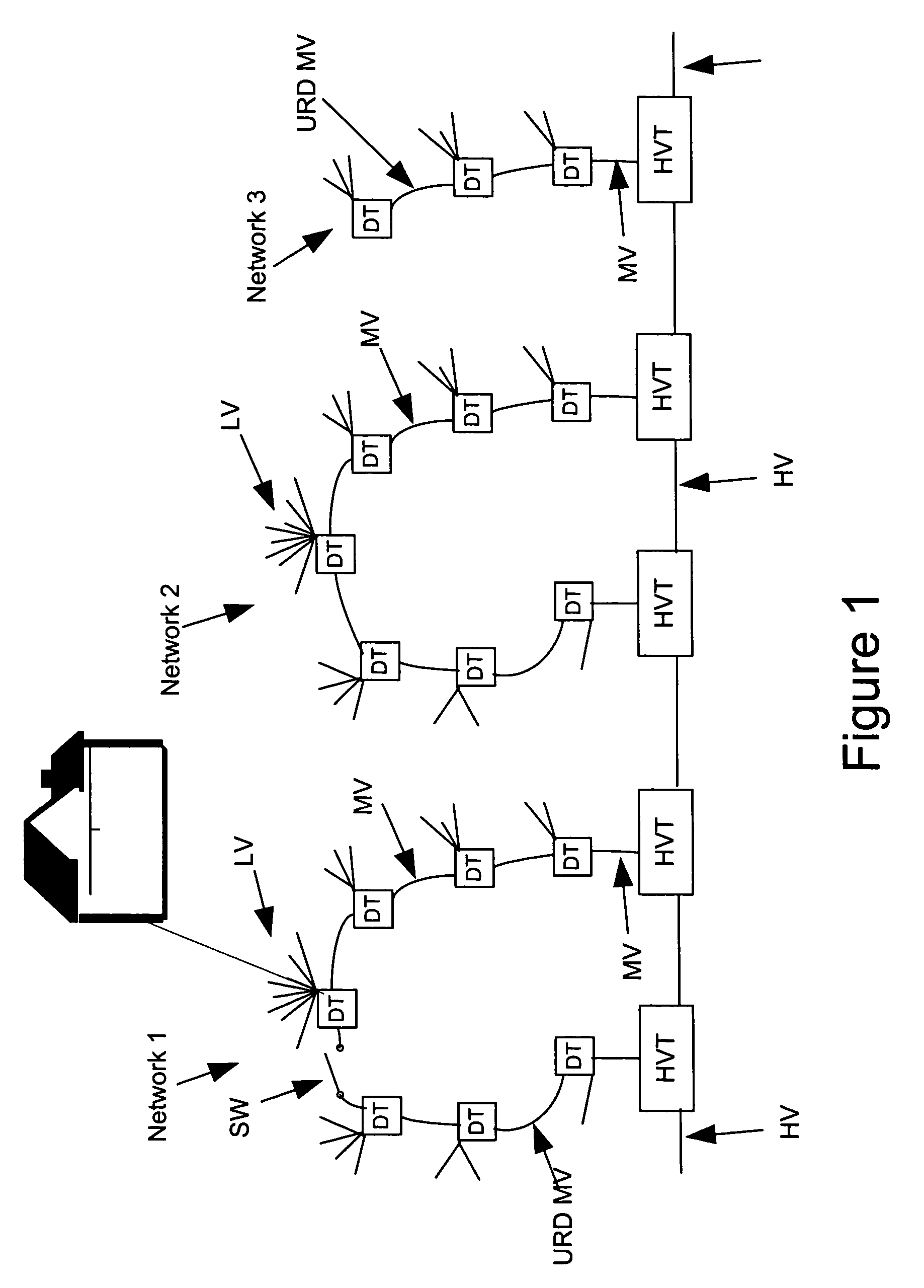
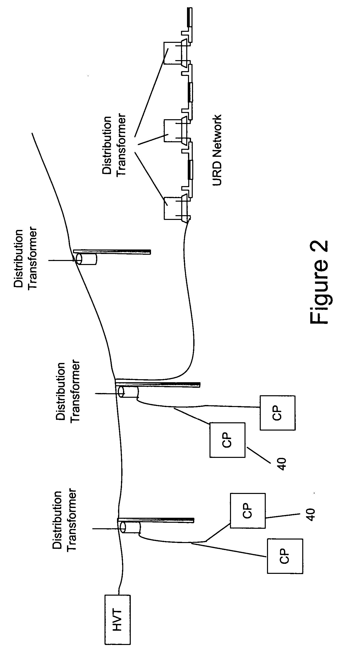
A device and method for providing power line communications via an underground residential distribution power system is provided. One embodiment of the present invention includes a medium voltage interface device that may include a first port configured to communicate over the power line and a network interface. A first amplifier may form part of a first communication path between the first port and the network interface and be configured to amplify data signals transmitted via the first port. In addition, a second amplifier may form part of a second communication path between the first port and the network interface and be configured to amplify data signals received via the first port. In addition, the embodiment may include a diplexer forming part of the first communication path between the first amplifier and the first port and forming part of the second communication path between the second amplifier and the first port. The device may include an electro-optic converter coupled to the network interface to convert between electrical and optic data signals, wherein the network interface is configured to communicate via one or more fiber optic conductors.

Description

CROSS REFERENCE TO RELATED APPLICATIONS [0001] This application is a continuation of, and claims priority to, U.S. patent application Ser. No. 11 / 254,887, filed Oct. 21, 2005, and is a continuation-in-part of, and claims priority to, U.S. patent application Ser. No. 10 / 973,493 filed Oct. 26, 2004, both of which are incorporated herein by reference in their entirety.FIELD OF THE INVENTION [0002] The present invention generally relates to data communications over a power distribution system and more particularly, to a power line communication system and method of using the same. BACKGROUND OF THE INVENTION [0003] Well-established power distribution systems exist throughout most of the United States, and other countries, which provide power to customers via power lines. With some modification, the infrastructure of the existing power distribution systems can be used to provide data communication in addition to power delivery, thereby forming a power line communication system (PLCS). In...

Claims


Application Information

Patent Timeline
Patent Type & Authority Applications(United States)
IPC IPC(8): G08B1/08H04B10/00H04L5/16G05B11/01
CPCH04B3/58H04J14/02H04J14/0226H04J14/0227H04J14/028H04J14/0282H04J14/0283H04L27/2601H04J14/0247H04J14/025H04J14/0252H04J14/0232H04J14/0246
Inventor GIDGE, BRETT D.RADTKE, WILLIAM O.
Owner CURRENT TECH
Learn More