Polarization detection

a polarization detection and light technology, applied in the field of polarization detection, can solve problems such as molecules falling during delay

Inactive Publication Date: 2006-08-31
RENCS ERIK V +1
View PDF34 Cites 38 Cited by
  • Summary
  • Abstract
  • Description
  • Claims
  • Application Information

AI Technical Summary

Benefits of technology

[0029] An optical device described herein can be used, e.g., to detect two orthogonally polarized light beams (e.g., ‘s’ and ‘p’ polarized beams) imaged onto the detector without the need for narrow spectral bandwidth, laser illumination, or narrow field-of-view.

Problems solved by technology

In solution, however, the molecule tumbles during the delay at a rate that is a function of its molecular size.

Method used


Image

  • Polarization detection
  • Polarization detection
  • Polarization detection

Examples


Embodiment Construction

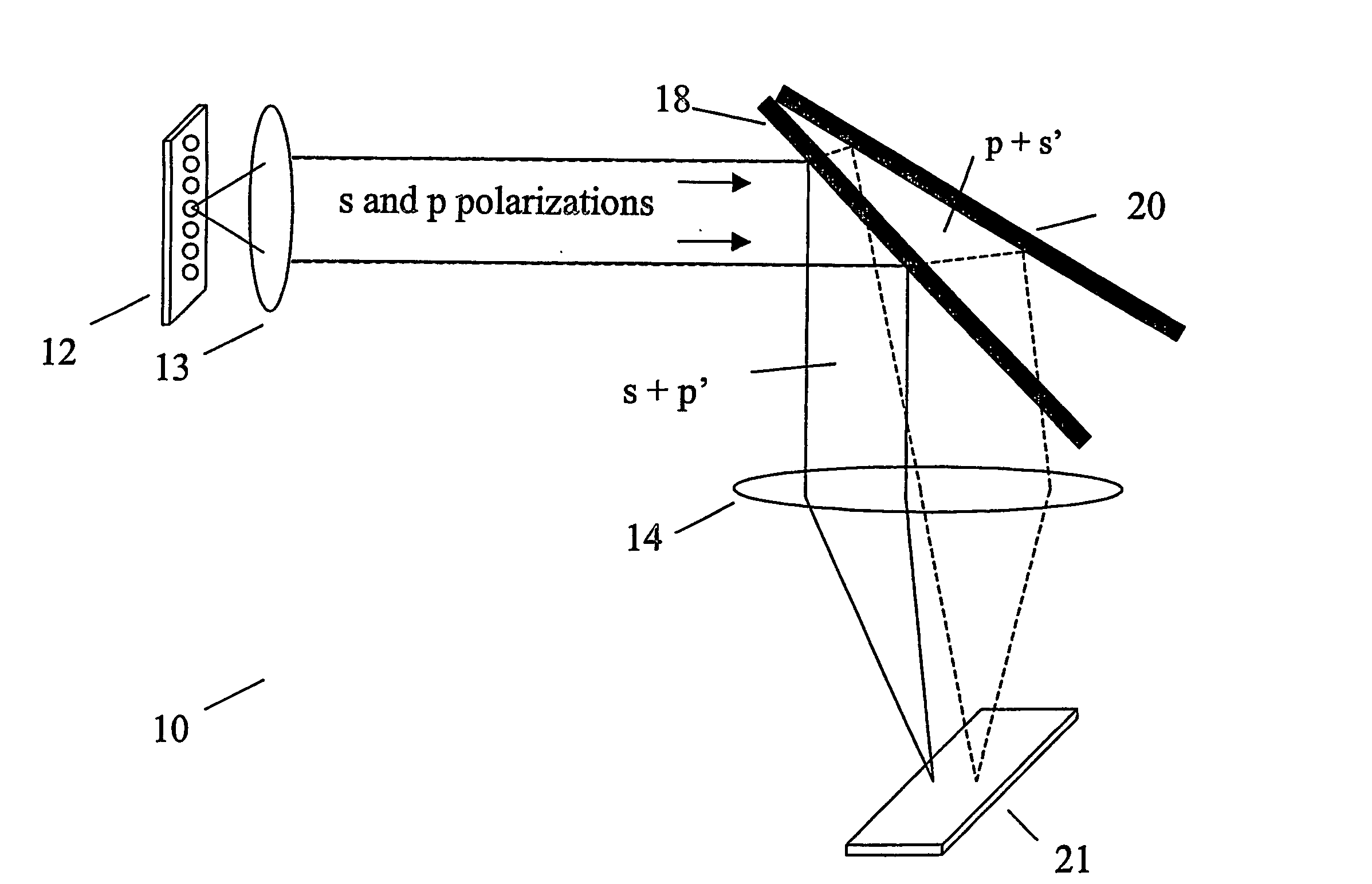
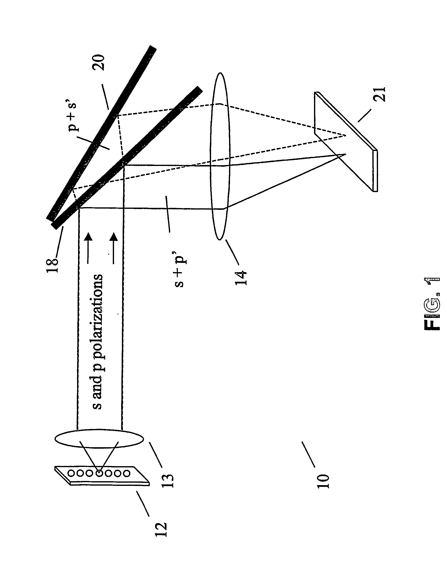
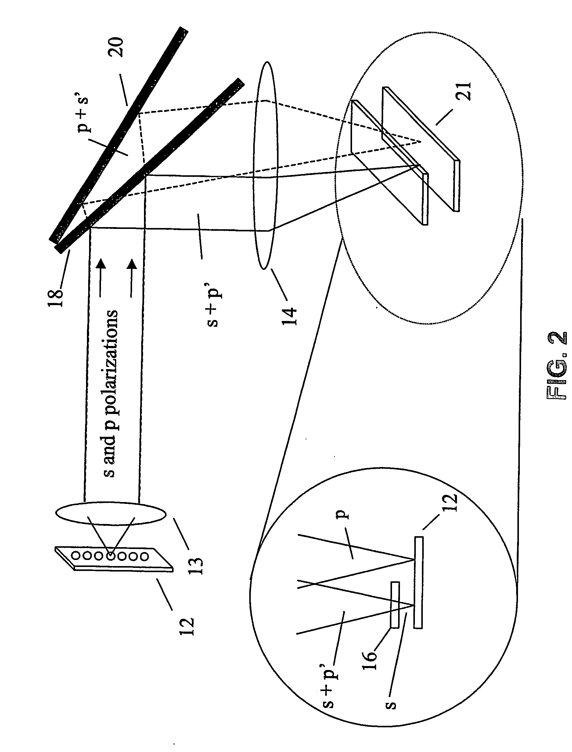
[0034] Referring to the exemplary system 10 in FIG. 1, the object 12 to be imaged is shown at the left. Light emitted from the object is collected and collimated by an optical system 13. The collected light is directed toward a reflective polarizer 18. The angle of incidence of the light at the reflective polarizer can be greater than 30°, e.g., about 45°. The polarizer 18 reflects substantially all light having s-polarization (i.e., light polarized perpendicular to the plane of FIG. 1) and transmits substantially all p-polarized light (i.e., light polarized parallel to the plane of FIG. 1). As used herein, substantially all light having a certain polarization state means at least 70% (e.g., at least 80%, 90%, 95%, 97%, 98%, 99%, 99.5%) of the light of that polarization state at the wavelength or wavelength range of interest.

[0035] In many implementations, in addition to reflecting s-polarized light, reflective polarizer 18 also reflects a portion (e.g., less than about 10% of the ...


PUM

PropertyMeasurementUnit
angleaaaaaaaaaa
wavelengthaaaaaaaaaa

Abstract

Disclosed is an optical device for receiving light having a wavelength between 400 nm and 680 nm. The device has a polarizing beam splitter (PBS) that comprises a substrate having a first and second surface, at least one of which being coated with a substantially parallel array of elongated conducting elements, wherein the PBS reflects light of a first polarity and transmits light of the opposite polarity; and a reflector positioned to reflect the opposite polarity light back through the PBS to the front surface, wherein the reflector does not substantially alter the polarity of light at any position. The device can be used to detect fluorescence polarization of a sample.

Description

CROSS-REFERENCE TO RELATED APPLICATIONS [0001] This application claims priority to U.S. Application Ser. No. 60 / 456,928, filed on Mar. 24, 2003, the contents of which are hereby incorporated by reference.BACKGROUND [0002] The invention relates to detection of polarized light. [0003] Polarized light has numerous applications in both natural and physical sciences. For example, detection of polarized light in a variety of wavelengths (including UV, visible, and infrared) can be used to obtain information about a sample. Similarly, polarized light can be used to send signals, e.g., liquid crystal displays manipulate the polarization state of light to alter the appearance of the display for a user. [0004] One exemplary application of polarized light is the detection of light emitted by a fluorescent compound. Properties of the fluorescent compound can be determined based on information about the detected light. In particular, fluorescence polarization (FP) provides information about the ...

Claims


Application Information

Patent Timeline
Patent Type & Authority Applications(United States)
IPC IPC(8): G01J4/00C12QC12Q1/68
CPCG01J3/02G01J3/0224G01J3/10G01J3/4406G01J3/447G01J4/04G01N21/21G01N21/6445G01N21/645G01N21/6452G01N2021/6419G01N2021/6421G01N2021/6484G02B27/283
Inventor RENCS, ERIK V.OLEKSY, JEROME E.
Owner RENCS ERIK V
Why Eureka
Try Eureka