Light-emitting diode backlight assembly and liquid crystal display device using the same

a technology of light-emitting diodes and backlight assemblies, which is applied in the direction of display devices, lighting and heating apparatus, instruments, etc., can solve the problems of difficult to achieve uniform light dispersion efficiency, display images may become stained, and display brightness is not uniform, so as to prevent light loss

Inactive Publication Date: 2006-08-31
LG DISPLAY CO LTD
View PDF21 Cites 62 Cited by
  • Summary
  • Abstract
  • Description
  • Claims
  • Application Information

AI Technical Summary

Benefits of technology

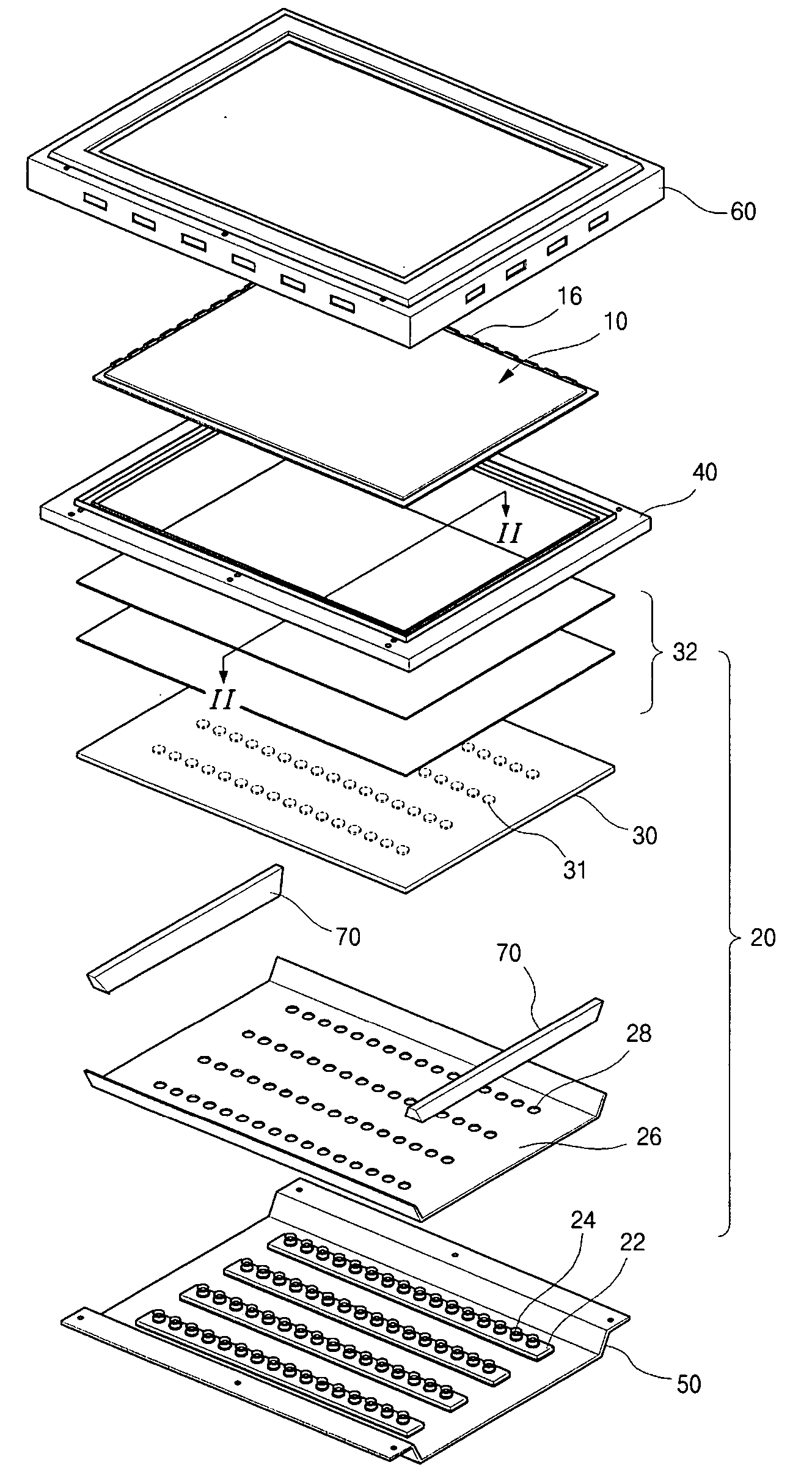
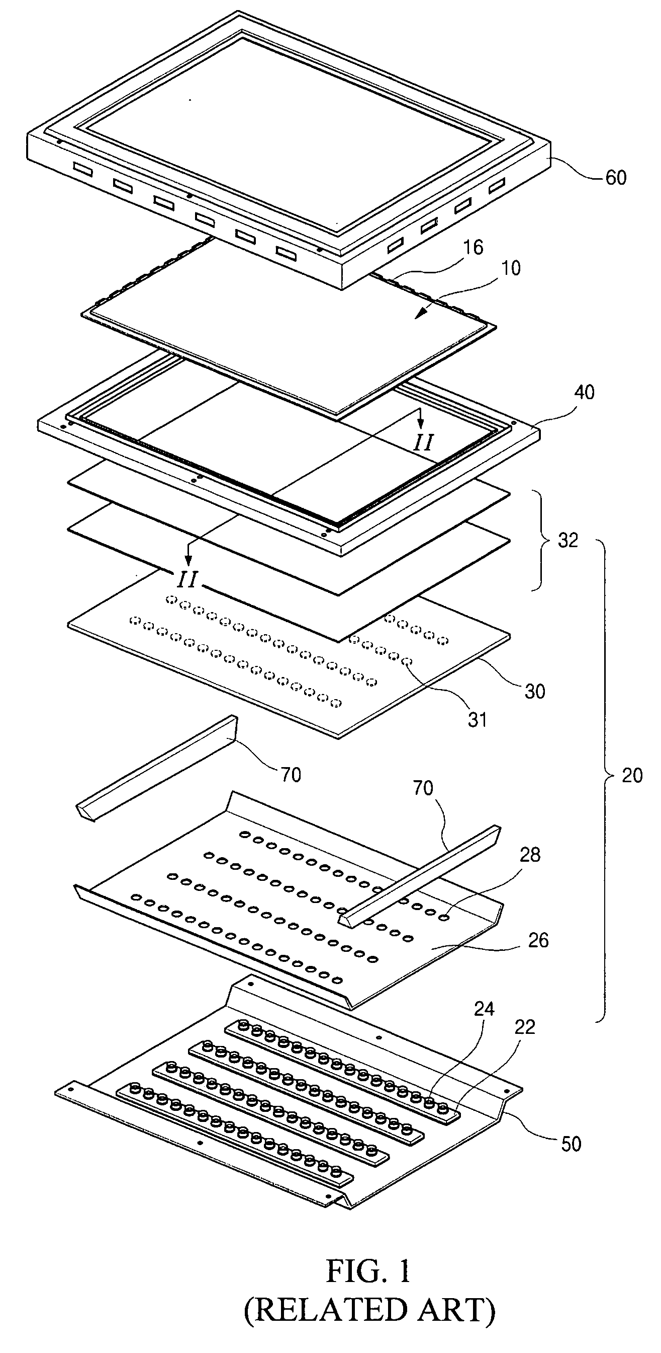
[0016] In another aspect, an LCD device employing an LED backlight assembly according to the present invention is provided. The LED backlight assembly further includes a reflecting sheet having a plurality of through-holes corresponding to the plurality of LED lamps. In addition to the LED backlight assembly, the LCD device includes an LCD panel over the LED backlight assembly, a bottom cover covering a rear side of the LED backlight assembly, and a main cover disposed between the liquid crystal display panel and the LED backlight assembly. A top cover covers the LCD panel and is connected to the main cover. The main cover is connected to the bottom cover forming a space to enclose the backlight assembly to prevent loss of light.

Problems solved by technology

There are several problems associated with LCD devices employing an LED backlight assembly according to the related art.
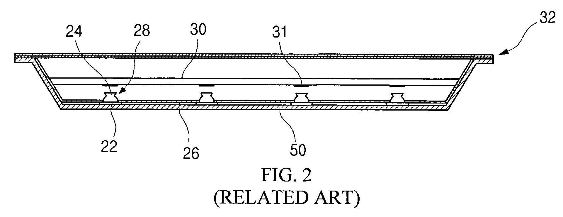
First, in spite of the use of reflecting dots 31 and optical sheets 32, it is difficult to achieve uniform light dispersion efficiency.
For example, the displayed images may become stained or they may exhibit non-uniform brightness.
However, if the transparent window 30 and the LED lamps 24 are too close, they may crash into each other and break when outer stresses, such as impact or vibration are applied.

Method used


Image

  • Light-emitting diode backlight assembly and liquid crystal display device using the same
  • Light-emitting diode backlight assembly and liquid crystal display device using the same
  • Light-emitting diode backlight assembly and liquid crystal display device using the same

Examples


Embodiment Construction

[0025]FIG. 3 is a perspective view depicting a liquid crystal display (LCD) device including an LED backlight assembly according to an embodiment of the present invention. In FIG. 3, a backlight assembly 120 is disposed at a rear side of the liquid crystal display panel 110. The main cover 140, a rectangular frame of a resin mold, is disposed between the backlight assembly 120 and the liquid crystal display panel 110. The bottom cover 150 covers and holds the backlight assembly 120 in place. The main cover 140 disposed at the rear side of the liquid crystal display panel 110 is connected to the bottom cover to prevent loss of light. A top cover 160, covering the front side of the liquid crystal display panel 110, is connected to the main cover 140 and the bottom cover 150.

[0026] The liquid crystal display panel 110 produces images. The liquid crystal display panel 110 includes first and second substrates 112 and 114 attached to each other with a liquid crystal material layer interp...


PUM


Abstract

An LCD device includes an LED backlight assembly, a liquid crystal display panel over the LED backlight assembly, a bottom cover covering a rear side of the LED backlight assembly, a reflecting sheet on an inner side of the bottom cover, the reflecting sheet having a plurality of through-holes corresponding to the plurality of LEDs, a main cover enclosing edges of the liquid crystal display panel and the LED backlight assembly, and a top cover covering edges of a front side of the liquid crystal display panel and combined with the main cover. The LED backlight assembly includes a plurality of LED lamps, a diffusion plate spaced apart from the plurality of LED lamps and having a light transmittance within a range of about 50% to about 90%, and a plurality of optical sheets over the diffusion plate. The LED assembly may be used in a method for providing a planar light source to an LCD panel in an LCD device.

Description

[0001] This application claims the benefit of priority under 35 U.S.C. § 119 to Korean Patent Application No. 2005-0016574, filed Feb. 28, 2005, which is hereby incorporated by reference in its entirety. FIELD OF THE INVENTION [0002] The present invention relates to a liquid crystal display (LCD) device. More particularly, the present invention relates to a light-emitting diode (LED) backlight assembly, a liquid crystal display (LCD) device including the LED backlight assembly, and a method of using the LED backlight assembly to provide a planar light source in an LCD device. DISCUSSION OF THE RELATED ART [0003] Our information-based society has created a demand for flat panel display (FPD) devices. FPD devices include plasma display panels (PDPs), field emission display (FED) devices, electroluminescent display (ELD) devices, liquid crystal display (LCD) devices, and so on. Since they are small, lightweight and have low power consumption, FPD devices are taking the place of cathode...

Claims


Application Information

Patent Timeline
Patent Type & Authority Applications(United States)
IPC IPC(8): F21V7/04
CPCG02F1/133603G02F1/133605G02F1/133606G02F1/133611G02F1/1335
Inventor BANG, JU-YOUNG
Owner LG DISPLAY CO LTD
Why Eureka
Try Eureka