X-ray apparatus

a technology of x-ray apparatus and x-ray tube, which is applied in the direction of mechanical apparatus, x-ray tubes, bearing cooling, etc., can solve the problems of rapid increase in the temperature of the bearing in a short time, easy generation of heat by the statator, etc., and achieve the effect of improving the heat radiation characteristic and stable output of x-rays

Active Publication Date: 2006-08-31
CANON ELECTRON TUBES & DEVICES CO LTD
View PDF4 Cites 13 Cited by
  • Summary
  • Abstract
  • Description
  • Claims
  • Application Information

AI Technical Summary

Benefits of technology

[0013] It is an object of the present invention to improve a heat radiation characteristic and to output X-rays sta...

Problems solved by technology

However, when a dynamic pressure plain bearing is used, a stator easily genera...

Method used


Image

  • X-ray apparatus
  • X-ray apparatus
  • X-ray apparatus

Examples


Embodiment Construction

[0027] Hereinafter, an embodiment of the present invention will be explained in detail with reference to the accompanying drawings.

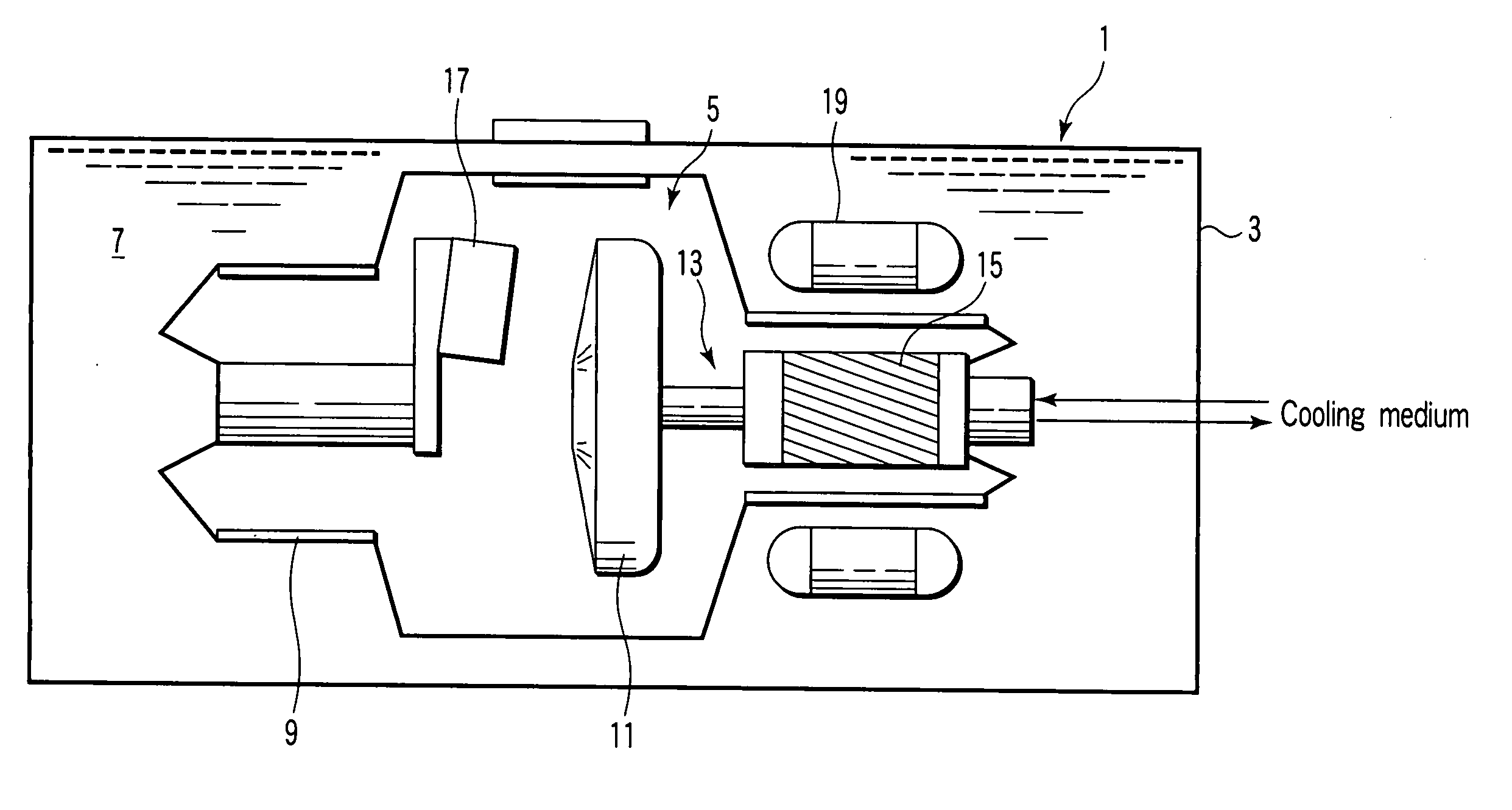
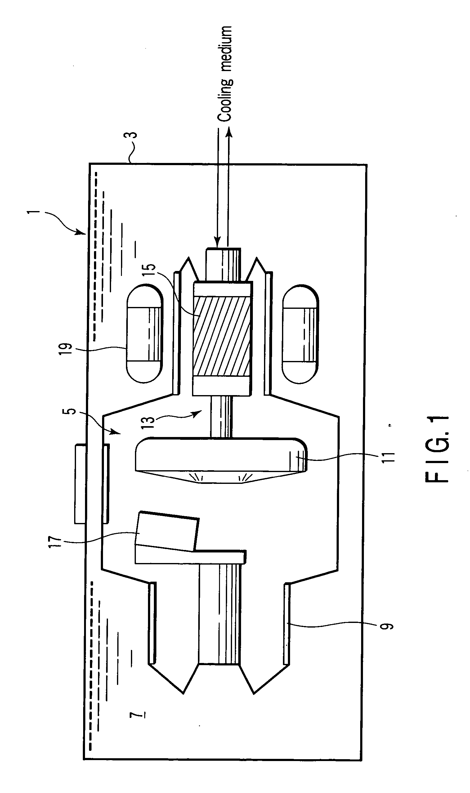
[0028] As shown in FIG. 1, an X-ray apparatus 1, which is incorporated in an X-ray image diagnostic apparatus or a non-destructive inspection apparatus, for example, and radiates X-rays to be applied to an object or an inspection object, has a housing 3, and an X-ray tube main body 5 capable of radiating X-rays with predetermined intensity to a predetermined direction.

[0029] The X-ray tube main body 5 is housed at a predetermined position in the housing 3 through a non-oil / fat cooling liquid or well-know insulating oil, that is, a cooling medium 7, which includes water as a main component and has an electrical conductivity controlled to be lower than a predetermined value.

[0030] The X-ray tube main body 5 has an enclosure (vacuum vessel) 9, an anode target (anode) 11 which is provided in the enclosure 9 and radiates X-rays when an electron impinges, a...


PUM


Abstract

The present invention is characterized by supporting a stator to generate a magnetic field and an anode target by a dynamic pressure plain bearing using a liquid metal, and cooling at least the inside of the dynamic pressure plain bearing and an enclosure containing an anode target by circulating one kind of cooling medium, in a rotary X-ray tube apparatus which obtains X-rays by impinging an electron on an anode by rotating an anode target.

Description

CROSS REFERENCE TO RELATED APPLICATIONS [0001] This is a Continuation Application of PCT Application No. PCT / JP2004 / 015386, filed Oct. 18, 2004, which was published under PCT Article 21(2) in Japanese. [0002] This application is based upon and claims the benefit of priority from prior Japanese Patent Application No. 2003-358275, filed Oct. 17, 2003, the entire contents of which are incorporated herein by reference.BACKGROUND OF THE INVENTION [0003] 1. Field of the Invention [0004] The present invention relates to an X-ray apparatus, and a rotating anode X-ray tube applied to an X-ray apparatus. [0005] 2. Description of the Related Art [0006] An X-ray apparatus using a rotary anode X-ray tube is composed of a rotary anode X-ray tube main body which contains a rotatably supported anode target in a vacuum enclosure, a stator coil which supplies a driving magnetic field from the outside of the X-ray tube main body to a rotor connected to the anode target, and a housing which contains th...

Claims


Application Information

Patent Timeline
IPC IPC(8): H01J35/10H01J35/26H01J35/24H01J35/28F16C37/00H05G1/04
CPCF16C37/002H01J35/101H01J2235/106H01J2235/1208H01J2235/1275H01J2235/168H05G1/04H05G1/025H01J35/104
Inventor ANNO, HIDEROKITADE, KOICHIKITAMI, TAKAYUKINAKAMUTA, HIRONORISATO, MANABU
Owner CANON ELECTRON TUBES & DEVICES CO LTD
Why Eureka
Try Eureka