Method of fabricating pliant workpieces, tools for performing the method and methods for making those tools

a technology of pliant workpieces and tools, applied in the direction of manufacturing tools, grinding machine components, edge grinding machines, etc., can solve the problems of difficult or impossible known prior art techniques and tools that were hard on pliant workpieces, and increased downtime for tooling changes. , to achieve the effect of reducing process monitoring requirements and downtime for tooling changes, dimensional stability and precision workpieces are difficult or impossible, and dimensional stability and precision

Inactive Publication Date: 2006-08-31
NEFF CHARLES E
View PDF54 Cites 2 Cited by
  • Summary
  • Abstract
  • Description
  • Claims
  • Application Information

AI Technical Summary

Benefits of technology

[0008] The present invention provides unique tools and methods for processing pliant workpieces such as automotive accessory belts that have grooves and lands. Tools constructed in accordance with this invention and utilized in accordance with this invention to make pliant workpieces have been reported to provide from 5 to 10 times the life of a diamond grinding tool, to dramatically reduce the process monitoring requirements and downtime for tooling changes and to permit higher production rates. While flycutting with tungsten carbide knives permits production speeds much higher than diamond wheels while running, that process requires frequent monitoring and more frequent downtime for tooling changes. Known prior art techniques and tools were hard on the pliant workpieces. They distorted the workpiece during processing and made dimensional stability and precision workpieces difficult or impossible. Utilizing the present invention, tool speeds of 10,000 feet per minute and feed rates of 10 inches per second have been achieved in production operations with greatly enhanced tool life.

Problems solved by technology

While flycutting with tungsten carbide knives permits production speeds much higher than diamond wheels while running, that process requires frequent monitoring and more frequent downtime for tooling changes.
Known prior art techniques and tools were hard on the pliant workpieces.
They distorted the workpiece during processing and made dimensional stability and precision workpieces difficult or impossible.

Method used


Image

  • Method of fabricating pliant workpieces, tools for performing the method and methods for making those tools
  • Method of fabricating pliant workpieces, tools for performing the method and methods for making those tools
  • Method of fabricating pliant workpieces, tools for performing the method and methods for making those tools

Examples


Embodiment Construction

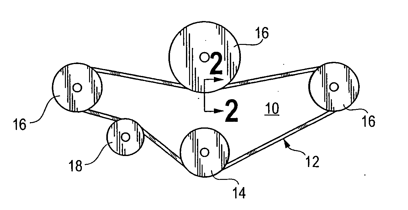
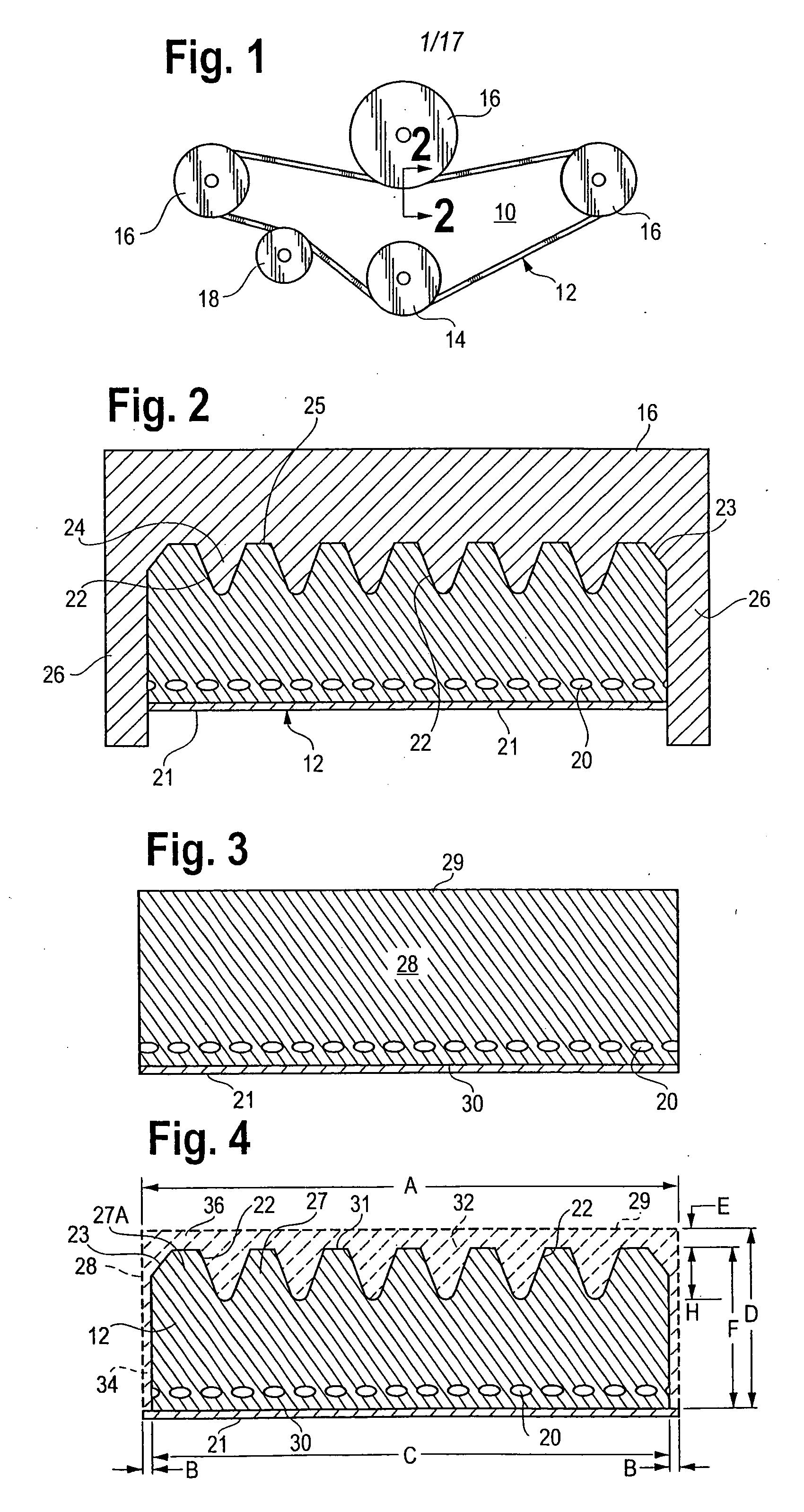
[0045] The invention disclosed herein is set forth in the following description, is illustrated in the attached drawings and is the subject of the attached claims. The invention includes an abrasive tool, a method of making the tool and a method for removing material from a workpiece, especially a pliant workpiece. Material is removed by contact and relative motion between a working surface of the tool and an operative surface of the workpiece in a direction to produce a precision profile comprising an elongate groove configuration in the workpiece. The abrasive tool is especially useful in manufacturing products of compliant rubber-like materials. The method involves removing material from an elongate, non-metallic workpiece to produce a precise operative face with a precision tapered groove, a back face and opposed sides connecting the faces. The particular workpiece selected to illustrate preferred embodiments of the invention hereinafter is an automotive accessory drive belt. Th...


PUM

PropertyMeasurementUnit
tool speedsaaaaaaaaaa
cutting angleaaaaaaaaaa
speedaaaaaaaaaa

Abstract

An improved method of manufacturing automotive accessory drive belts or other workpieces of pliant material which have a grooved operative face, a tool having an abrasive ramp configuration for performing said improved method and a method of manufacturing said tool with the abrasive ramp configuration.

Description

REFERENCE TO RELATED PATENT APPLICATION [0001] This patent application is a divisional of U.S. patent application Ser. No. 10 / 635,374 which was based on and claimed the benefits of U.S. Provisional Application No. 60 / 401,816 filed on Aug. 7, 2003.FIELD OF THE INVENTION [0002] This invention pertains to precision methods for operating on surfaces of pliant non-metallic workpieces, to methods of manufacturing tools for such operations and to tools for performing such operations. BACKGROUND OF THE INVENTION [0003] Historically, processing pliant materials such as rubber compounds and elastomers has presented serious difficulties. This has been especially true when the processing resembled grinding to shape or finish a part as practiced on hard materials such as metals, thermosetting resins and the like. The resilience of the workpiece has produced a variable and unpredictable interface between workpiece and tool and consequent unpredictable dimensions and surface finish of the workpiec...

Claims


Application Information

Patent Timeline
Patent Type & Authority Applications(United States)
IPC IPC(8): B24B1/00B24B19/22
CPCB24B19/22
Inventor NEFF, CHARLES E.
Owner NEFF CHARLES E
Why Eureka
Try Eureka