Bone fixation apparatus

a technology of bone fixation and bone, which is applied in the field of surgical systems, can solve the problems of limited adaptability of connective structures with respect to a plurality, and the ease with which surgeons install clamping systems

Inactive Publication Date: 2006-08-31
LEE DAVID +2
View PDF84 Cites 75 Cited by
  • Summary
  • Abstract
  • Description
  • Claims
  • Application Information

AI Technical Summary

Problems solved by technology

One of the problems with the application of a spinal fixation system is the limited adjustability of the connective structures with respect to a plurality of spaced apart bone screws wh

Method used


Image

  • Bone fixation apparatus
  • Bone fixation apparatus
  • Bone fixation apparatus

Examples


Embodiment Construction

[0029] Detailed descriptions of one or more preferred embodiments are provided herein. It is to be understood, however, that the present invention may be embodied in various forms. Therefore, specific details disclosed herein are not to be interpreted as limiting, but rather as a basis for the claims and as a representative basis for teaching one skilled in the art to employ the present invention in any appropriate system, structure or manner.

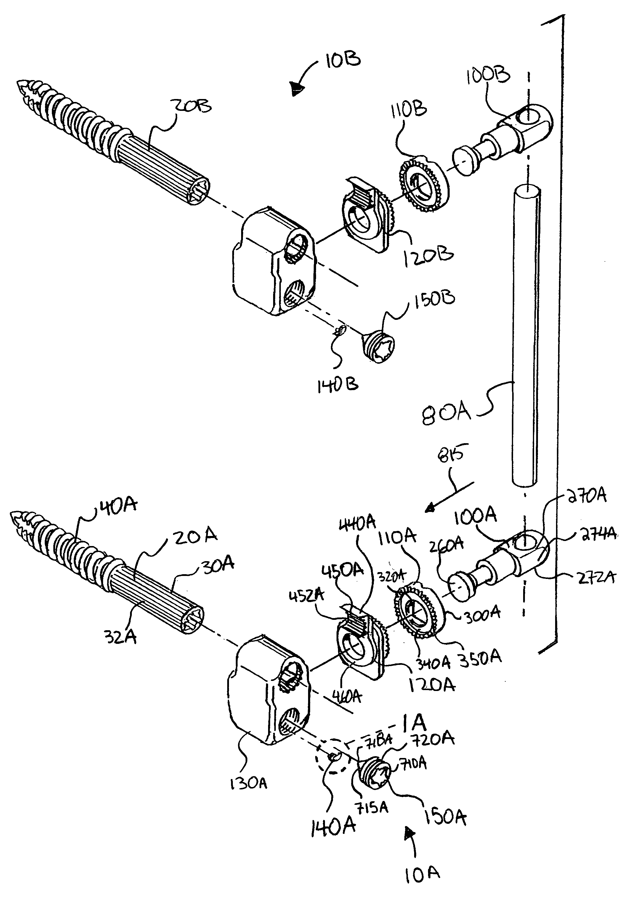
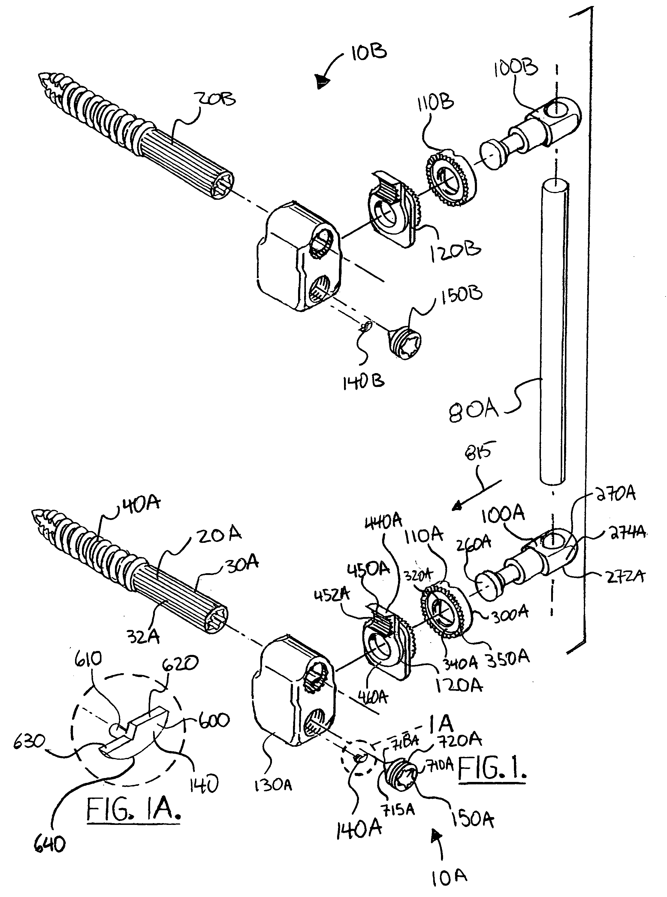
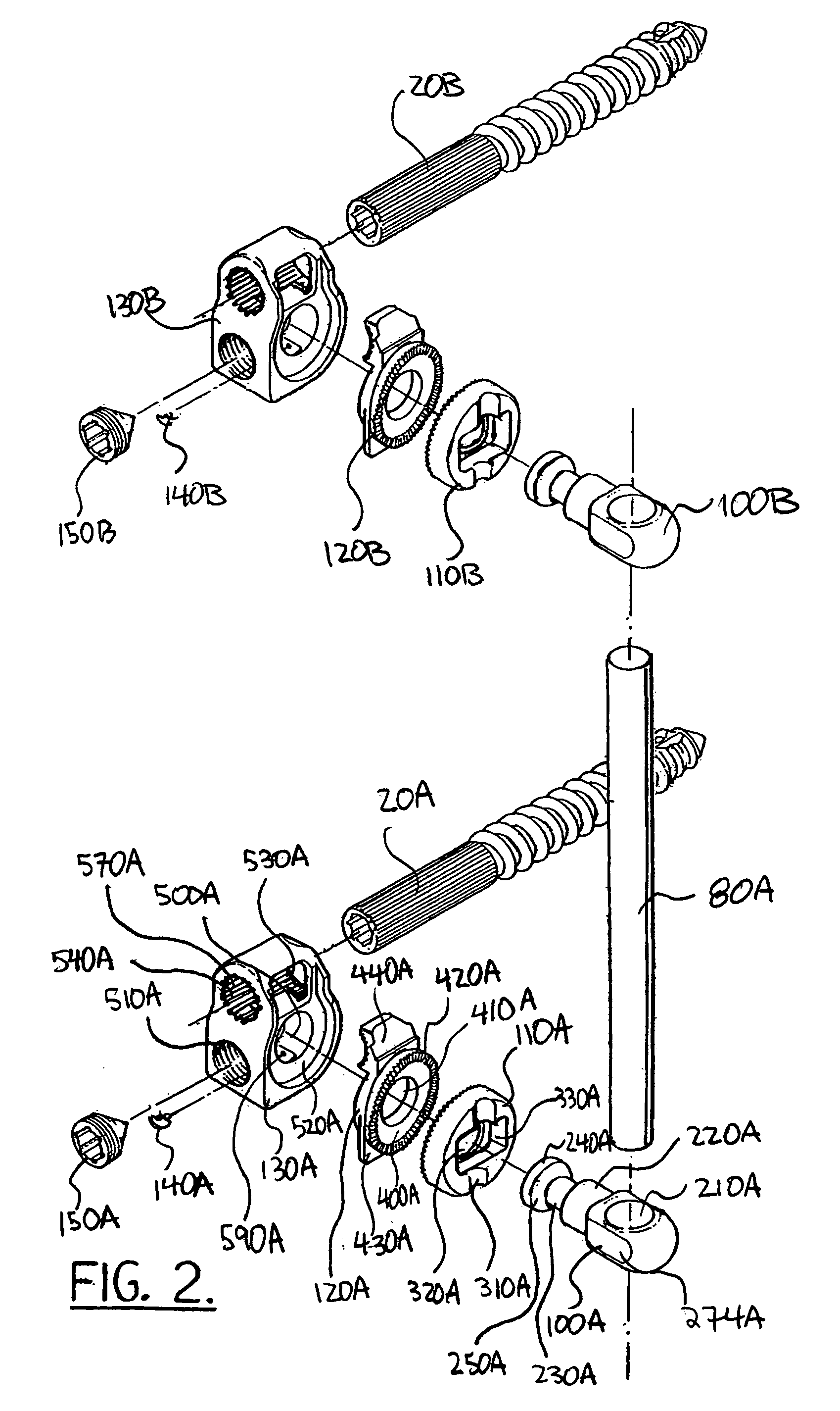
[0030]FIGS. 5-7 illustrate the process of fusing two vertebrae 800, 810 using a plurality of clamps 10A, 10B, 10C, and 10D of the construction shown in FIGS. 1-4. All clamps 10 can be of substantially identical construction (however, clamps 10A, 10B are shown as mirror images of clamps 10C, 10D to have both rods 80A, 80B set between the clamps). The operation of clamp 10A will be described in specific detail. In each case, for an effective fusion, vertebra 800 is held in contact with vertebra 810. In its simplest form, clamp 10A can be mechani...


PUM


Abstract

What is provided is a fixation system that offers a strong and stable construct for maximum fusion augmentation and yet is versatile enough for any patient and is easy to use. Disclosed is a connection assembly for connecting a spinal implant, the assembly comprising: a body, the body including a body opening for receiving at least a portion of a first connector; a swivel having first and second ends and being operatively connected to the body, the first end including a swivel opening for receiving at least a portion of a second connector; a locking plate having an arm at least partially extending into the body opening; a locking unit operatively connected to the body and contacting the second end of the swivel; and whereby activation of the locking unit causes the arm to engage the first connector and swivel opening to engage the second connector thereby preventing relative rotation between the first and second connectors.

Description

CROSS-REFERENCE TO RELATED APPLICATIONS [0001] Priority of U.S. provisional patent application serial number 60 / 651,314, filed Feb. 9, 2005, is hereby claimed. This application is incorporated herein by reference.STATEMENT REGARDING FEDERALLY SPONSORED RESEARCH OR DEVELOPMENT [0002] Not applicable REFERENCE TO A “MICROFICHE APPENDIX”[0003] Not applicable BACKGROUND [0004] The present invention relates to surgical systems and more particularly relates to an improved bone or spinal fixation apparatus in the form of a strong and stable construct for maximum fusion augmentation with improved versatility and ease of use, and including an improved rotation and adjustment system. [0005] There are a number of surgical procedures which require a fixation of portions of the spine with respect to one another. Typically, bone screws are employed in the fixation of the spine. The implantation of bone screws is a surgical procedure which involves the formation of one or more surgical openings in ...

Claims


Application Information

Patent Timeline
IPC IPC(8): A61F2/30
CPCA61B17/7035A61B17/7037Y10T29/49826A61B17/7041A61B17/7038
Inventor LEE, DAVIDGRAHAM, ERICPAYNE, JAMES P. JR.
Owner LEE DAVID
Why Eureka
Try Eureka