
Task scheduling device, method, program, recording medium, and transmission medium for priority-driven periodic process scheduling

a technology of task scheduling and process scheduling, applied in the direction of multi-programming arrangements, program control, instruments, etc., can solve the problems of affecting the efficiency of cpu resources, user discomfort, and inability to execute specific tasks that are controlled to wake up and sleep cyclically, so as to achieve effective utilization of cpu resources, low priority, and balanced manner

Inactive Publication Date: 2006-08-31
PANASONIC CORP
View PDF5 Cites 101 Cited by
  • Summary
  • Abstract
  • Description
  • Claims
  • Application Information

AI Technical Summary

Benefits of technology

[0006] In view of the above problems residing in the prior art, an object of the present invention is to provide a task scheduling technology that enables to realize processing of a task to be prioritized and a task of lower priority in a well-balanced manner, while effectively utilizing the resource of a CPU.

Problems solved by technology

For instance, a user may feel uncomfortable if start of execution of a task is exceedingly delayed in response to an input entered by the user.
However, in such a technique, it is impossible for a specific task that is controlled to wake up and sleep cyclically to be executed while it is put to sleep.
Specifically, in a circumstance that processing of the other task(s) is not required while the specific task is put to sleep, there is a blank time when no active task exists, which hinders efficient use of the resource of a CPU.

Method used


Image

  • Task scheduling device, method, program, recording medium, and transmission medium for priority-driven periodic process scheduling
  • Task scheduling device, method, program, recording medium, and transmission medium for priority-driven periodic process scheduling
  • Task scheduling device, method, program, recording medium, and transmission medium for priority-driven periodic process scheduling

Examples


example of first embodiment

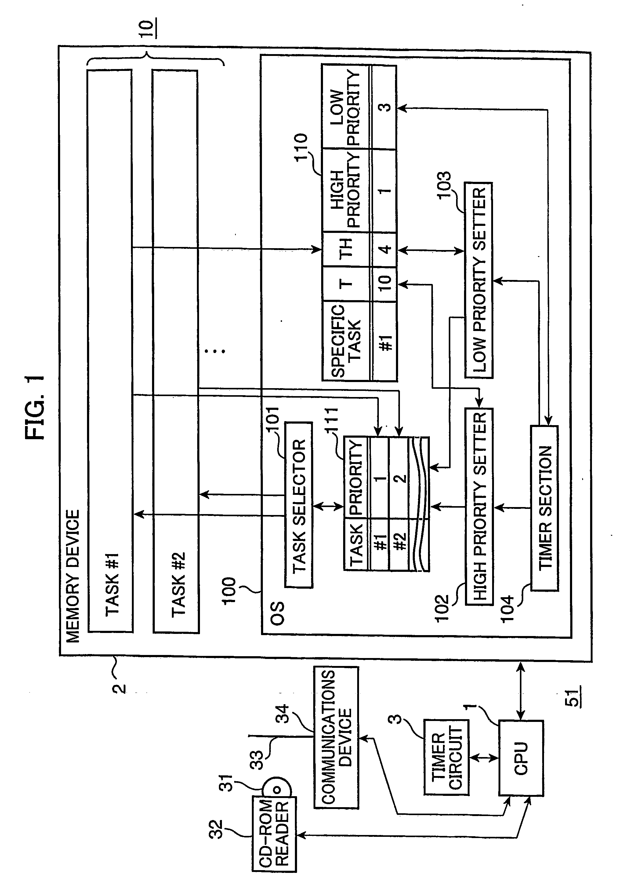
[0065]FIG. 4 is a block diagram showing an example of the task scheduling device 51 according to the first embodiment. A computer equipped with the task scheduling device 51A comprises an input device 4, an input interface 5, and an output device 6, in addition to components equivalent to the components of the computer shown in FIG. 1. The input device 4 is a keyboard, and the output device 5 is a display for outputting audio and displaying images, for instance.

[0066] An OS 100A for realizing the task scheduling device 51A in cooperation with a CPU 1 includes a buffer manager 130 and a device driver 140, in addition to components equivalent to the components of the OS 100 (see FIG. 1). The buffer manager 130 manages a buffer 131 provided in a memory region of a memory device 2. The buffer 131 temporarily stores data sent from a task #1 before outputting to the output device 5. The buffer manager 130 is constructed as a system call, for instance. In this example, in the case where d...

first embodiment

Modification of First Embodiment

[0082]FIG. 10 is a block diagram showing a configuration of a modification of the task scheduling device as the first embodiment. The task scheduling device 51B is different from the task scheduling device 51 (see FIG. 1) in that a high priority periodical setting section 102A and a low priority periodical setting section 103A (hereinafter, simply called as “high priority setter 102A” and “low priority setter 103A”, respectively) corresponding to the high priority setter 102 and the low priority setter 103 of the task scheduling device 51 are provided in a task #1, and that a timer section 104A is provided in place of the timer section 104 in accordance with the alteration of the arrangement. The task scheduling device 51B can be realized by cooperation of respective components of a program including the high priority setter 102A and the low priority setter 103A in the task #1, and respective components of an OS 100B with a CPU 1.

[0083] The high prio...

second embodiment

Various Modifications of Second Embodiment

[0103] There are proposed various modifications as shown in FIGS. 15 through 19, other than the embodiment shown in FIG. 12, as arrangements relating to a processing of switching the priority of the specific task from a high priority to a low priority. The task scheduling device 52A shown in FIG. 15 is configured such that a processed amount judger 120A is provided in an OS 100D and a task #1 in a bridging manner. Specifically, a processed amount resetter 121A is provided in the OS 100D, and a processed amount comparator 122 is provided in the task #1. Similarly to the timer section 104, a timer section 104C is realized as an interrupt handler which executes an interrupt processing every time interval T0, for instance. The timer section 104C boots the processed amount resetter 121A in the OS 100D every time interval T. Alternatively, the processed amount resetter 121A itself may be realized as an interrupt handler which executes an interrupt...


PUM


Abstract

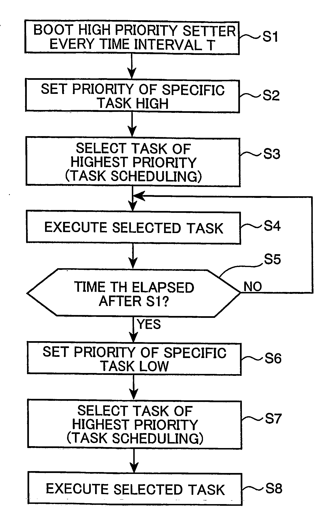
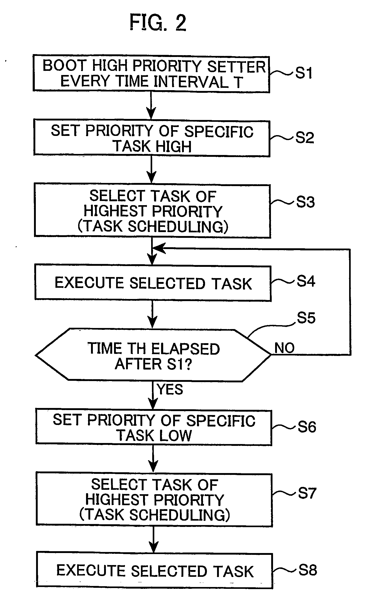
A high priority setter 102 writes the first priority (high priority) of a specific task #1 recorded in a specific task table 110 every time interval T, as the priority of the task #1 in a task priority table 111. Thereafter, when a time duration TH shorter than the time interval T elapsed, a low priority setter 103 writes the second priority (low priority) of the specific task #1 recorded in the specific task table 110, as the priority of the task #1 in the task priority table 111. The second priority is set lower than the first priority. A task selector 101 selects a task whose priority is set the highest among the tasks 10 recorded in the task priority table 111, as a specific task to be executed. Thus, the processing of the specific task #1 is securely executed during the time duration TH every time interval T, and the execution of the specific task #1 is allowed to continue if it is judged that there is no other task to be executed during the rest of the time interval T other than the time duration TH, by setting the first priority sufficiently high.

Description

TECHNICAL FIELD [0001] The present invention relates to a task scheduling device for performing task scheduling in a multitask environment, a task scheduling method, a task scheduling program, a recording medium, and a transmission medium. BACKGROUND ART [0002] Computers have been utilized not only in the form of apparatus whose primary purpose is information processing, such as large-scaled computers and personal computers, but also in the form of applied devices such as various consumer electronic devices, and mobile phones. Some of the consumer electronic devices loaded with a computer are required to perform a predetermined processing every predetermined time interval. In case of handling streaming video or audio data, frames of the streaming data are designed to be processed every predetermined time unit, e.g., 10 ms. In such a case, unless necessary data processing is executed with respect to each of the frames within a predetermined time, continuous video or audio output is n...

Claims


Application Information

Patent Timeline
Patent Type & Authority Applications(United States)
IPC IPC(8): G06F9/46G06F9/48
CPCG06F9/4887
Inventor AMANO, KATSUSHIGEMIZUYAMA, MASASHIGE
Owner PANASONIC CORP
Learn More