Cylinder head structure of engine

a technology of cylinder head and engine, which is applied in the direction of machines/engines, cylinders, mechanical equipment, etc., can solve the problems of not providing more appropriate cooling function for respective portions, reducing the temperature around the ignition plug, and unable to properly cool down, so as to improve the cooling function of the exhaust-side portion efficiently

Inactive Publication Date: 2006-09-07
MAZDA MOTOR CORP
View PDF8 Cites 26 Cited by
  • Summary
  • Abstract
  • Description
  • Claims
  • Application Information

AI Technical Summary

Benefits of technology

[0010] The present invention has been devised in view of the above-described problems, and an object of the present invention is to provide the cylinder head structure of an engine that can improve the cooling function of the exhaust-side portion efficiently as well as the intake-side portion, providing the proper cooling function of the ignition-plug hole wall.

Problems solved by technology

The art disclosed in the above-described publication, however, just attempts to increase the coolant flow speed at the combustion-chamber side entirely in the water jacket, and so would not provide more appropriate cooling function for respective portions.
Further, it is necessary to reduce properly the temperature around the ignition plug, but the art in the publication would not consider the cooling function of the ignition-plug hole wall itself either.
However, any measures for properly cooling the portion are not disclosed in the above-described art.

Method used


Image

  • Cylinder head structure of engine
  • Cylinder head structure of engine
  • Cylinder head structure of engine

Examples


Embodiment Construction

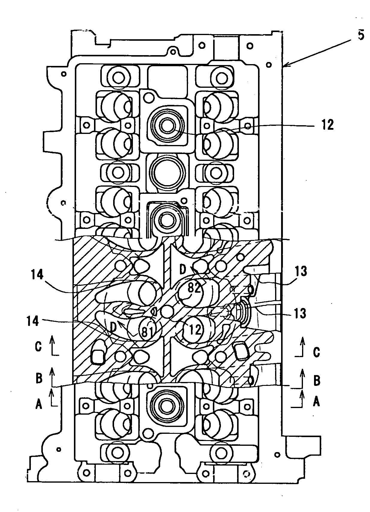
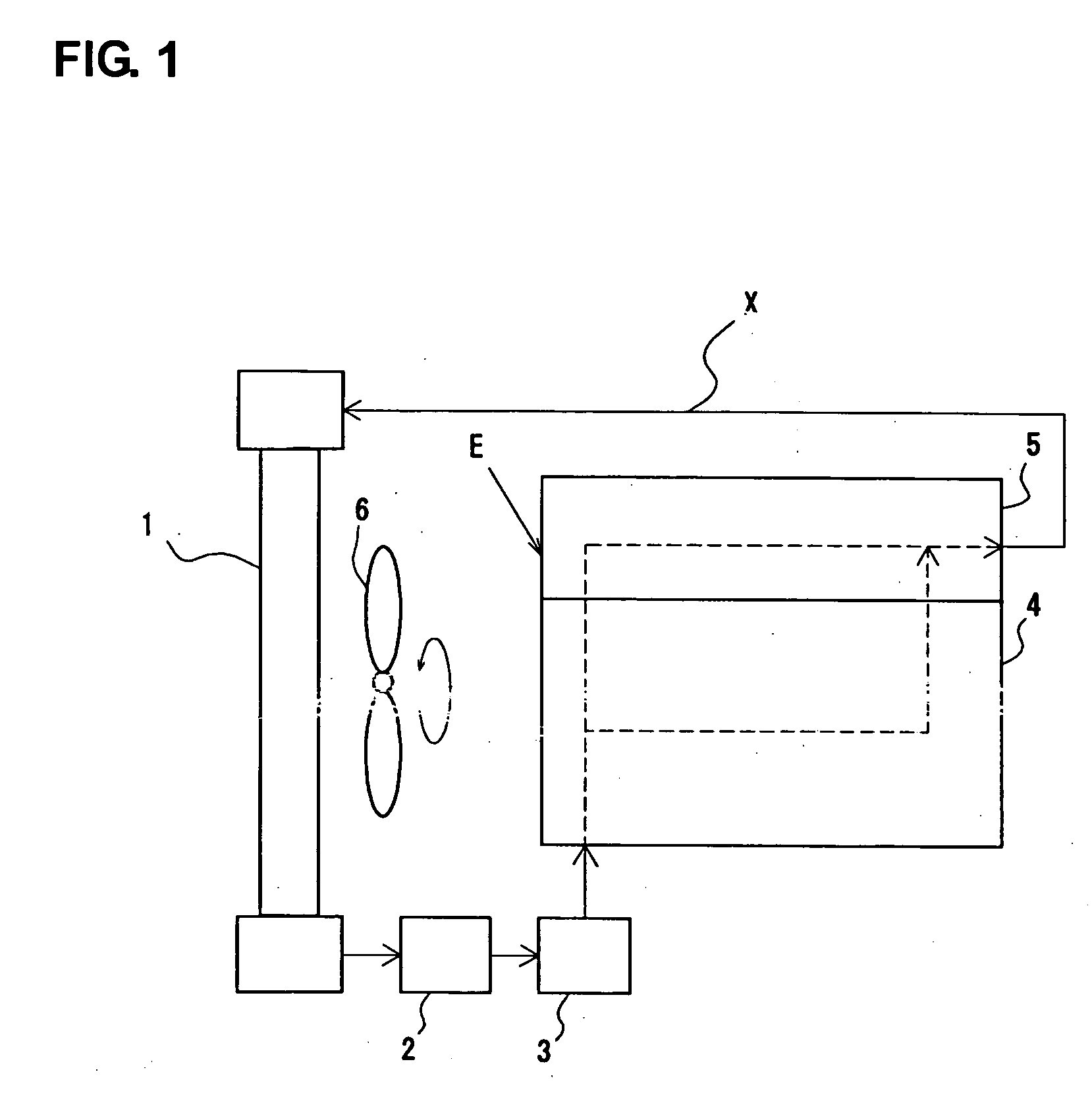
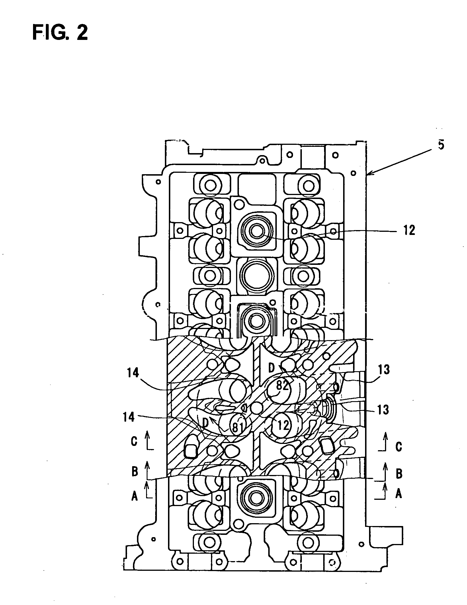
[0046] Hereinafter, an embodiment of the present invention will be described referring to the accompanied drawings. FIG. 1 is a schematic diagram of a coolant path X of an engine E with a cylinder head according to the present invention.

[0047] The coolant path X of the engine E comprises a coolant circulation path that includes a radiator 1 to cool heated coolant, a thermostat 2 to control the flow volume of the coolant, a water pump 3 to supply the coolant in the path, a cylinder block 4 to be cooled by the coolant, and a cylinder head 5 to be cooled by the coolant likewise. The engine E is cooled by the coolant that is circulated in this path. Herein, a cooling fan 6 is provided to cool the radiator 1.

[0048] The flow volume of the coolant in the coolant path X is adjusted to a specified volume by the water pump 3 and others. Thus, the cooling function of the engine E depends on how to control distribution of the coolant in the path.

[0049] According to the present embodiment, a ...


PUM


Abstract

The first flow-restriction vertical bead narrowing the coolant flow is provided to increase the flow speed at this portion. The coolant passage opens at the flow-in area between the exhaust ports. Thereby, the flow speed of the coolant at this area is increased, so the coolant in the coolant passage can be properly sucked due to the Venturi effect. As a result, the cooling function can be improved.

Description

BACKGROUND OF THE INVENTION [0001] The present invention relates to a cylinder head structure of an engine, particularly to a cylinder head of an engine that can improve the engine cooling function. [0002] An engine valve drive mechanism comprising two intake valves and two exhaust valves provided for each cylinder has been recently adopted to improve an intake and exhaust efficiency of the engine. [0003] The engine equipped with such a valve drive mechanism has been also desired to have a higher power as well as compactness of its engine body. Accordingly, some measures against a severe heat load due to the higher power have been required. [0004] In particular, it is important to improve the cooling function around the combustion chamber and the exhaust ports, and therefore some technologies for those have been proposed. [0005] For example, Japanese Patent Laid-Open Publication 2003-314357 discloses a structure that the cross section area of the plug tower portion (the cylindrical ...

Claims


Application Information

Patent Timeline
Patent Type & Authority Applications(United States)
IPC IPC(8): F01P3/02
CPCF01P3/16F02F1/40
Inventor YAMADA, TAKAYUKIHADAMA, KOUJI
Owner MAZDA MOTOR CORP
Why Eureka
Try Eureka