Deep water drilling with casing

a casing and wellhead technology, applied in the direction of drilling pipes, rotary drilling, borehole/well accessories, etc., can solve the problems of catching the drill string in the hole, affecting and affecting the operation etc., to achieve the effect of facilitating the engagement of the casing wellhead

Inactive Publication Date: 2006-09-07
WEATHERFORD TECH HLDG LLC
View PDF99 Cites 38 Cited by
  • Summary
  • Abstract
  • Description
  • Claims
  • Application Information

AI Technical Summary

Benefits of technology

[0019] In another embodiment, the conductor pipe and the casing may be placed into the earth as a nested casing strings assembly. A casing latch is used to couple the casing to the conductor pipe. In this respect, the conductor pipe rotated with casing during drilling. After conductor pipe is placed at target depth, the casing is released from the conductor pipe and is drilled further into the earth. In one embodiment, the casing is drilled until a wellhead on the casing is engaged with a wellhead of the conductor pipe. In another embodiment, a collapsible joint is provided on the casing to facilitate the engagement of the casing wellhead with the wellhead of the conductor pipe.

Problems solved by technology

In the earlier stages of casing placement, support for the riser is often unavailable.
If cement fills the rat hole, then the next drill string that goes through the cement in the rat hole may core it and the remaining cement, since it is unsupported could fracture and fall in on the drill string, thereby possibly trapping the drill string in the hole.
Because this occurs during the riserless stage, most of the weighted fluid will be lost to the open water.
Wells with these types of drilling hazards tend to fracture when the minimum drilling fluid weight needed to control shallow water flows and / or shallow gas flows is used.
Running large diameter casing in a predrilled hole presents several challenges.
One such challenge arises when the hole has low formation pore pressure.
In that instance, running the casing too fast could surge the well, i.e., put excessive pressure on the bore of the well, and cause the bore hole to fracture or break down a surrounding earth formation.
On drilling rigs, the extra time needed to run the casing may substantially increase the operating cost.

Method used


Image

  • Deep water drilling with casing
  • Deep water drilling with casing
  • Deep water drilling with casing

Examples


Embodiment Construction

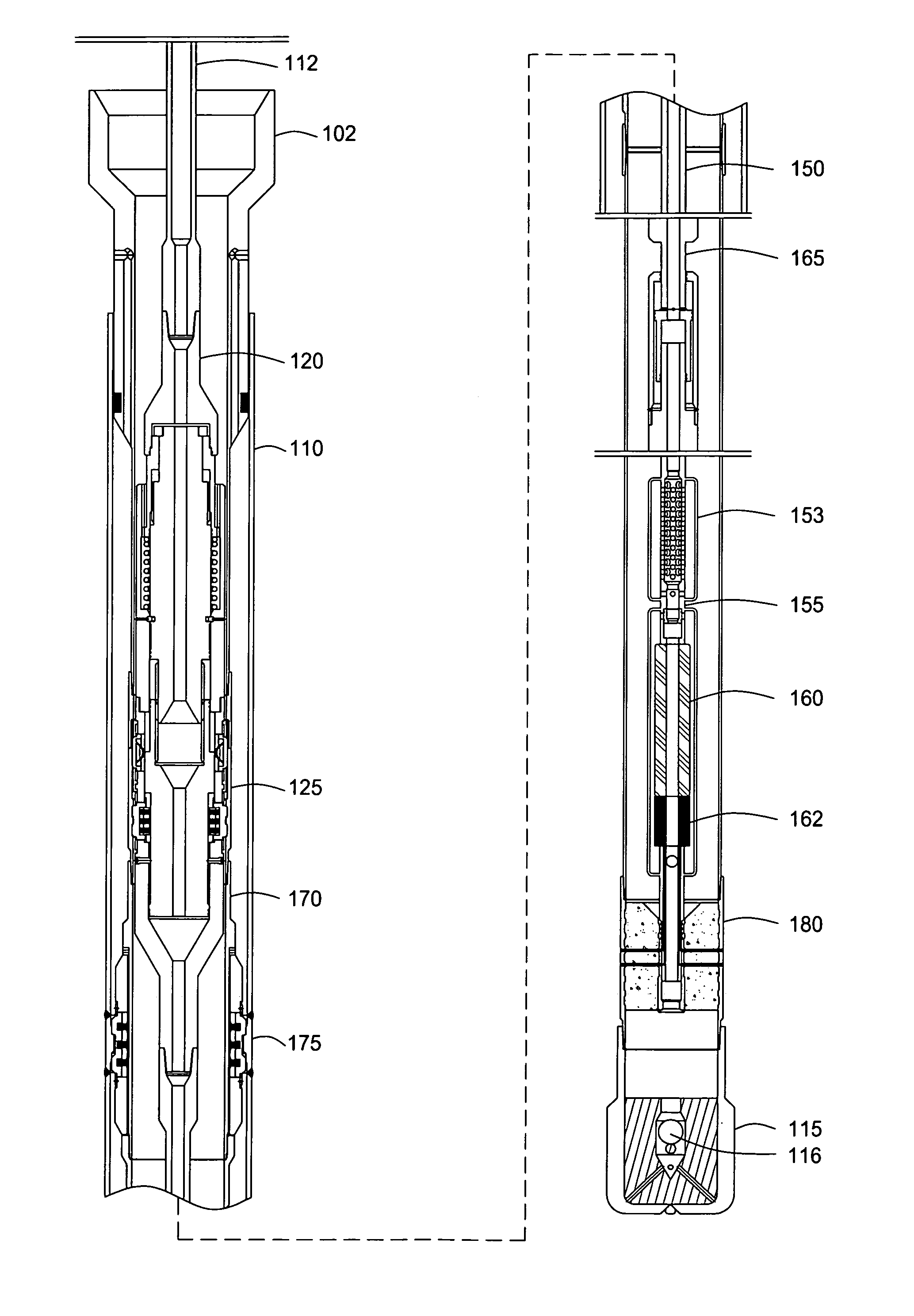
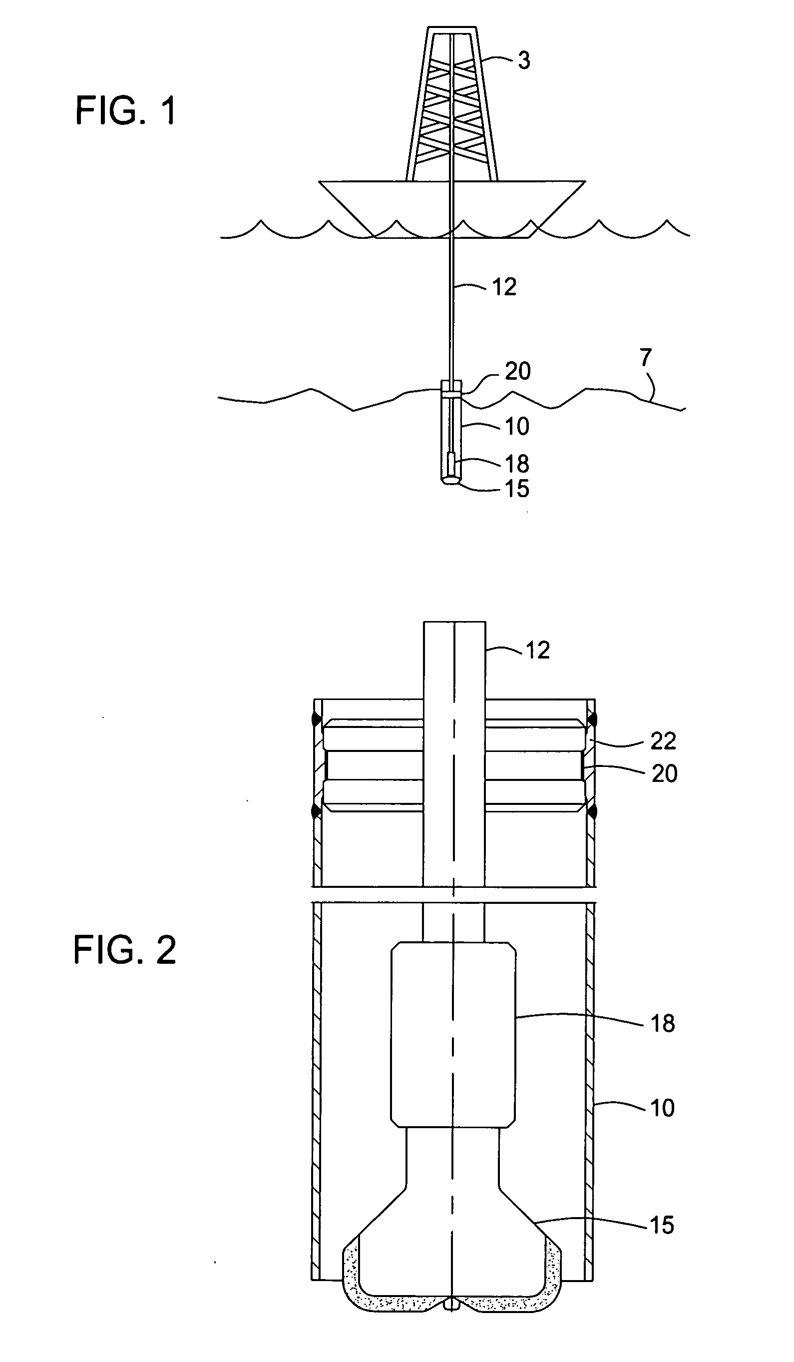
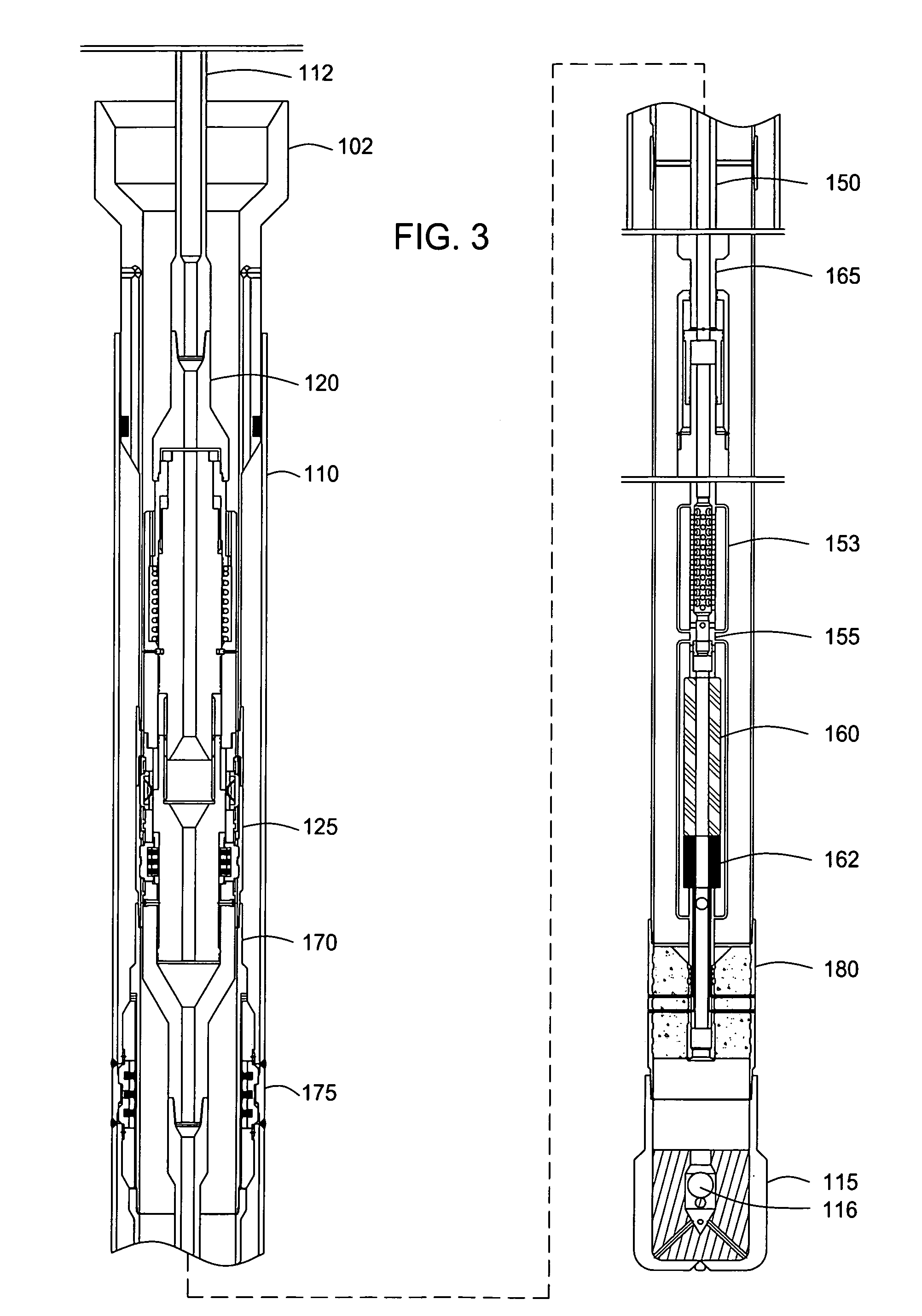
[0045] Embodiments of the present invention provide a method of placing casing in the earth beneath the water. In one embodiment, the method involves using casing as part of the drill string. In particular, the method involves drilling with casing in deep water.

[0046] In situations where the water depth is deeper than the length of drill casing being run, the drill string may be extended by adding drill pipe. In this respect, a connection crossover is used to connect the smaller diameter drill pipe to the casing. The crossover is adapted to transmit torque, axial, and tensile load from the drill pipe to the casing. The crossover is also adapted to detach from the casing to permit retrieval of the drill pipe and the crossover after the casing is placed at the desired location.

[0047] In one embodiment, a drilling latch 120 is used to facilitate the positioning of the drill casing 105 in the previously run conductor pipe 110 and drilling below the conductor pipe 110, as illustrated i...


PUM


Abstract

Methods and apparatus are provided to place a conductor pipe and a casing in a subsea environment. In one embodiment, a conductor pipe is jetted or drilled into the subsea floor. Thereafter, a casing drilling assembly comprising a drill casing and a drilling assembly is connected to the drill pipe using a crossover. The drilling assembly urged into the seafloor until a casing latch on the drilling assembly is engaged with a casing profile of the conductor pipe. During drilling, instrumentation in the drilling assembly may be used to measure geophysical data. The measured data may be used to optimize the drilling process. After the drill casing is engaged with the conductor pipe, cementing may be performed to set the drill casing.

Description

CROSS-REFERENCE TO RELATED APPLICATIONS [0001] This application claims benefit of co-pending U.S. Provisional Patent Application Ser. No. 60 / 657,221, filed on Feb. 28, 2005, which application is incorporated herein by reference in its entirety. [0002] This application is a continuation-in-part of co-pending U.S. patent application Ser. No. 11 / 063,459, filed on Feb. 22, 2005, which is a divisional of U.S. patent application Ser. No. 10 / 331,964, filed on Dec. 30, 2002, now U.S. Pat. No. 6,857,487, which patent and applications are incorporated herein by reference in their entirety. [0003] This application is also a continuation-in-part of co-pending U.S. patent application Ser. No. 10 / 775,048, filed on Feb. 9, 2004, which application is incorporated herein by reference in its entirety.BACKGROUND OF THE INVENTION [0004] 1. Field of the Invention [0005] Embodiments of the present invention generally relate methods and apparatus for drilling a well beneath water. More specifically, embod...

Claims


Application Information

Patent Timeline
Patent Type & Authority Applications(United States)
IPC IPC(8): E21B7/20
CPCE21B7/20E21B21/001E21B7/203
Inventor GIROUX, RICHARD L.REID, DOUGODELL, ALBERT C. IIGALLOWAY, GREGORY G.MURRAY, MARK J.
Owner WEATHERFORD TECH HLDG LLC
Why Eureka
Try Eureka