Operator safety device for a machine having sharp implements
- Summary
- Abstract
- Description
- Claims
- Application Information
AI Technical Summary
Benefits of technology
Problems solved by technology
Method used
Image
Examples
first embodiment
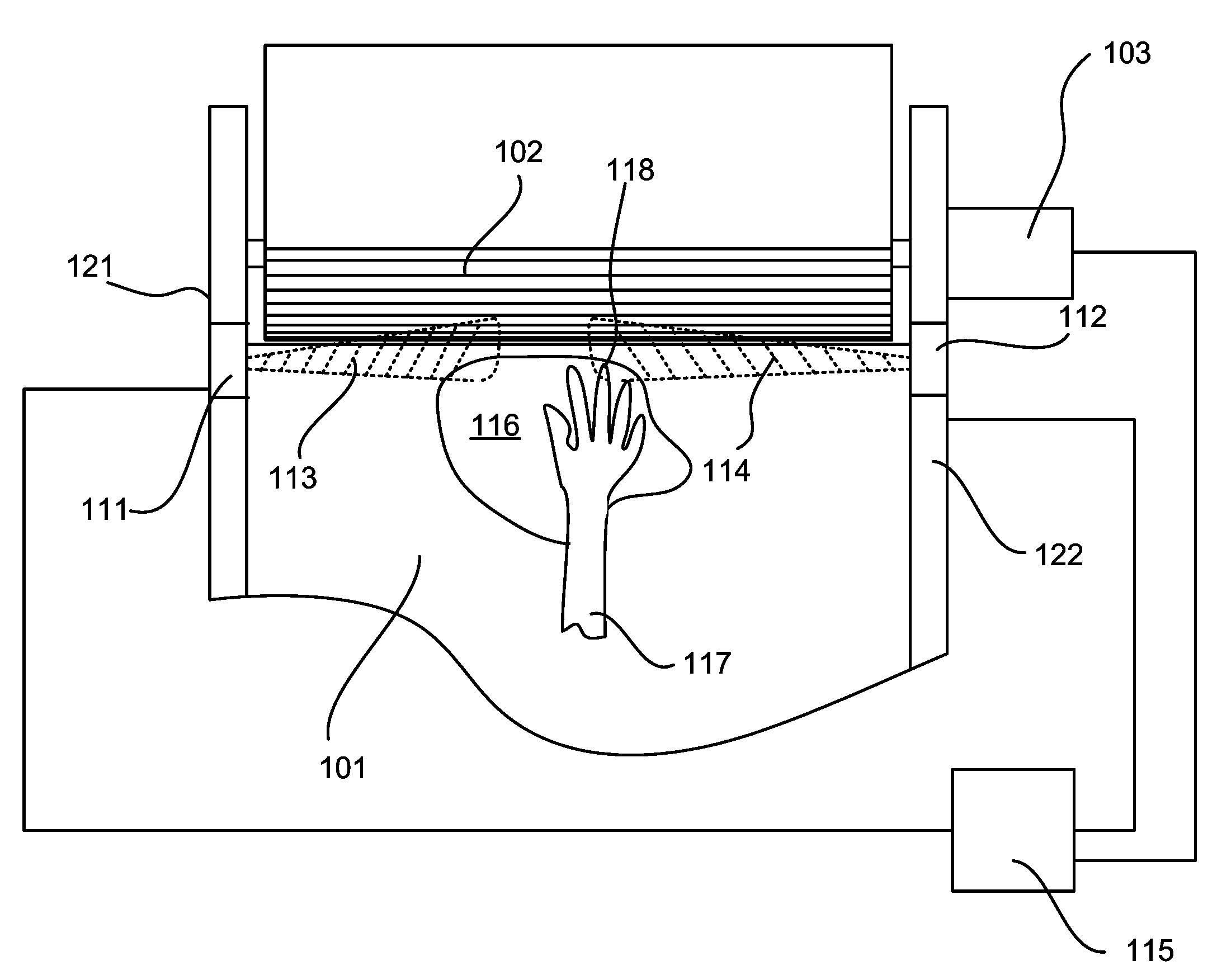
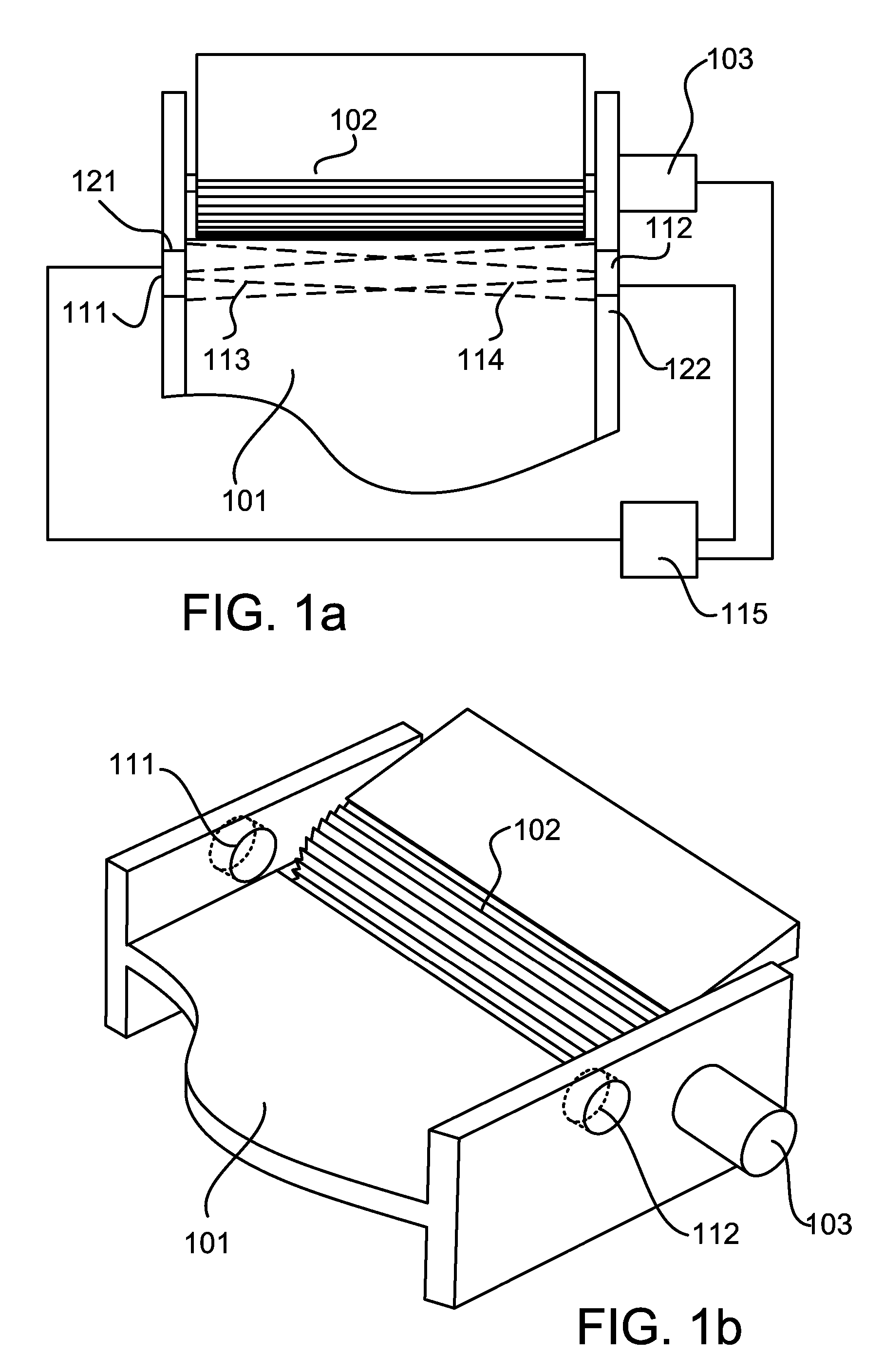
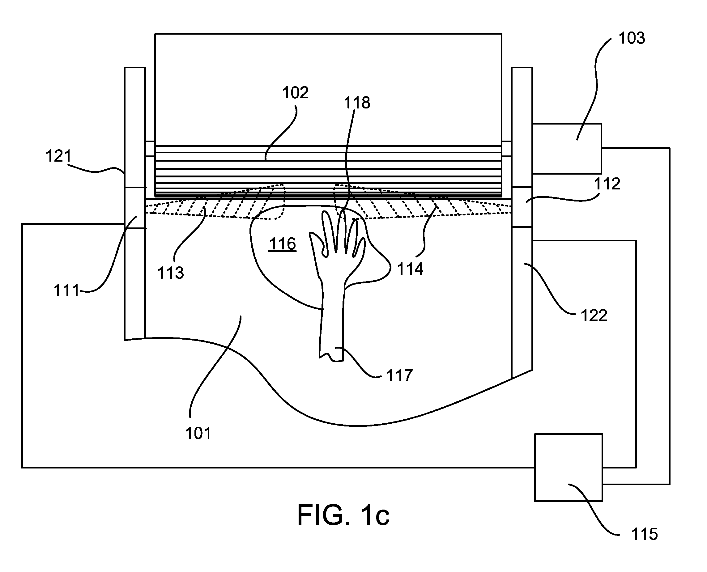
[0024]FIG. 1a illustrates a top view and FIG. 1b illustrates a perspective view of the invention, an operator safety device that utilizes thermal detection. The operator safety device is disposed as part of a machine 101 having a danger zone 102. The danger zone includes for example cutting knives or other sharp implements that are used for processing of meat or other products that may cause harm to an extremity of a human operator if they come in contact therewith. In such machines, the cutting knives or other sharp implements are typically motorized using a motor 103 that is controlled using a control signal provided from a control circuit 115 for enabling and disabling operation thereof.
[0025] The operator safety device preferably comprises a first thermal sensor 111, a second thermal sensor 112 and the control circuit 115. The first thermal sensor 111 is disposed at a first position 121 in vicinity of the danger zone 102 of a machine 101. The second thermal sensor 112 is dispose...
second embodiment
[0031]FIGS. 2a and 2b illustrates the invention, where a first thermal sensor is in the form of a first thermal imaging camera 211 and optionally a second thermal sensor is in the form of a second thermal imaging camera 212. The first thermal imaging camera 211 is disposed at a first position 221 in vicinity of a danger zone 102 of a machine 101. The second thermal imaging camera 212 is disposed at a second position 222 in vicinity of the danger zone 102 of the machine 101 and preferably faces the first thermal imaging camera 211. Each thermal imaging camera provides its own detection zone, 213 and 214 respectively (FIG. 2b), which overlap with each other. These overlapping detection zones 213 and 214 border the danger zone 102 of the machine 101 and preferably overlap a portion of the danger zone 102. A processor 219 disposed within a control circuit 215 is coupled to each of the thermal imaging cameras 211 and 212 to process the thermal information received therefrom. A switching ...
third embodiment
[0034]FIGS. 4a, 4b, 4c and 4d illustrate the invention, a dual laser and dual receiver system that is used to detect the presence of one of an animate object, such as an extremity 117 and 118 of a human operator, and an inanimate object. A first laser and receiver pair 411 is disposed at a first position 421 in vicinity of a danger zone 102 of a machine 101. A second laser receiver pair 412 is disposed at a second position 422 in vicinity of the danger zone 102 of the machine 101 and preferably faces the first laser receiver pair, as shown in FIGS. 4b and 4c. The first laser receiver pair 411 includes a first laser 411a and a first optical receiver 411b. The second laser receiver pair 412 includes a second laser 412a and a second optical receiver 412b. As shown in FIG. 4c, the lasers and optical receiver are aimed such that without an obstruction between the two laser receiver pairs 411 and 412 the first laser 411a is aimed at the second optical receiver 412b and the second laser 41...
PUM
 Abstract
Description
Claims
Application Information
 - R&D
- Intellectual Property
- Life Sciences
- Materials
- Tech Scout
- Unparalleled Data Quality
- Higher Quality Content
- 60% Fewer Hallucinations
Browse by: Latest US Patents, China's latest patents, Technical Efficacy Thesaurus, Application Domain, Technology Topic, Popular Technical Reports.
© 2025 PatSnap. All rights reserved.Legal|Privacy policy|Modern Slavery Act Transparency Statement|Sitemap|About US| Contact US: help@patsnap.com


