Coupling assembly with sterilizing chamber

a technology of coupling assembly and sterilizing chamber, which is applied in the field of valves, can solve the problems of complete system, loss of sterility, and compromise of sterility,

Active Publication Date: 2015-09-01
CHARGEPOINT TECH
View PDF12 Cites 0 Cited by
  • Summary
  • Abstract
  • Description
  • Claims
  • Application Information

AI Technical Summary

Benefits of technology

[0017]The valve of the present invention is able to operate in a complete sterile manner, by use of an ‘in situ’ sterilisation step applied before completion of each docking (i.e. when in said first configuration), regardless of how many times the valve is split open and re-docked, i.e. engaged and disengaged, ensuring sterile conditions on product or material contact surfaces.
[0037]During use, the assembly may be switched from the first to the second configuration to allow material to be transferred therethrough. Once the material has been transferred, the assembly is switched back to the first configuration and the surfaces which are to he exposed to the surrounding environment cleaned before disengaging the two valve portions so as to prevent the operator from being exposed to any residual material left on the exposable surfaces, and thus ensuring operator safety.

Problems solved by technology

Unfortunately, when one of these conventional known valves is split, sterility is lost or compromised as some of the critical surfaces of the valve and seats, when split into two halves, become exposed to the outside surrounding non-sterile atmosphere.
If the split valve is subsequently re-docked, and opened up for transfer of material, the entire system can lose sterility and result in product contamination.
The material being handled is often hazardous to health, owing to the increasing potency of many new active pharmaceutical ingredients (APIs).
Furthermore, the APIs may, in sufficient quantities, be hazardous to the health of an operator.
When using a split valve assembly, this can become difficult for an operator to handle in such contained environments.
However, isolators designed for containment and sterility combined together, maintaining a sterile and sealed environment, both for the integrity of the material being handled and an operator's health, can be very expensive.

Method used


Image

  • Coupling assembly with sterilizing chamber
  • Coupling assembly with sterilizing chamber
  • Coupling assembly with sterilizing chamber

Examples


Embodiment Construction

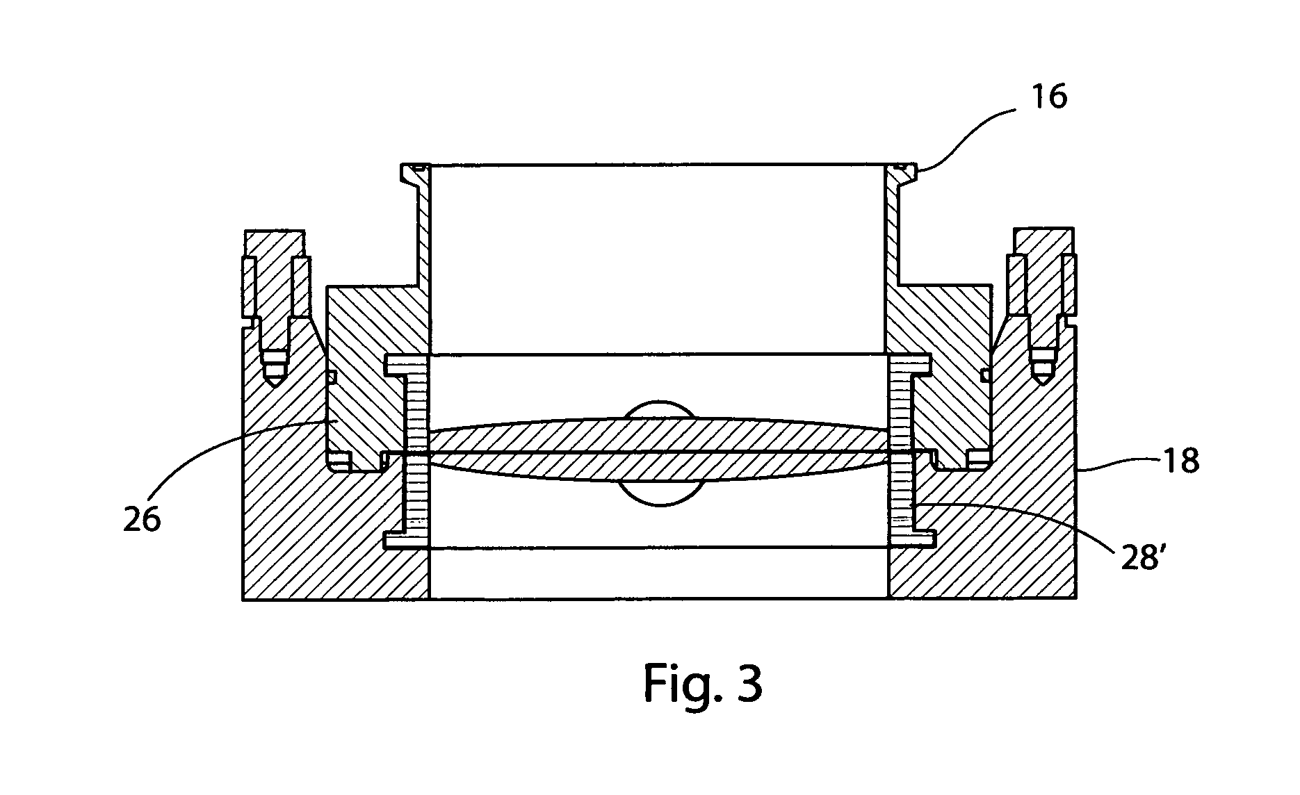
[0057](FIG. 4) One of the spindles 22 of the lower valve closure member 18 is adapted to be received by a further spindle 24 of actuator 26, whilst the housing of lower valve portion 18 has a bore receiving the other spindle 22′. Thus, the annular disc is journalled for rotation on the spindles 22,22′ and is moved by rotation of the spindle 24. An automatic actuator 26 is received on an opposite end to the annular disc of the spindle 24. A manual actuator can be used in an alternative embodiment.

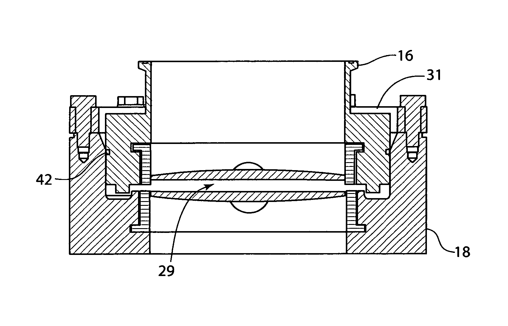
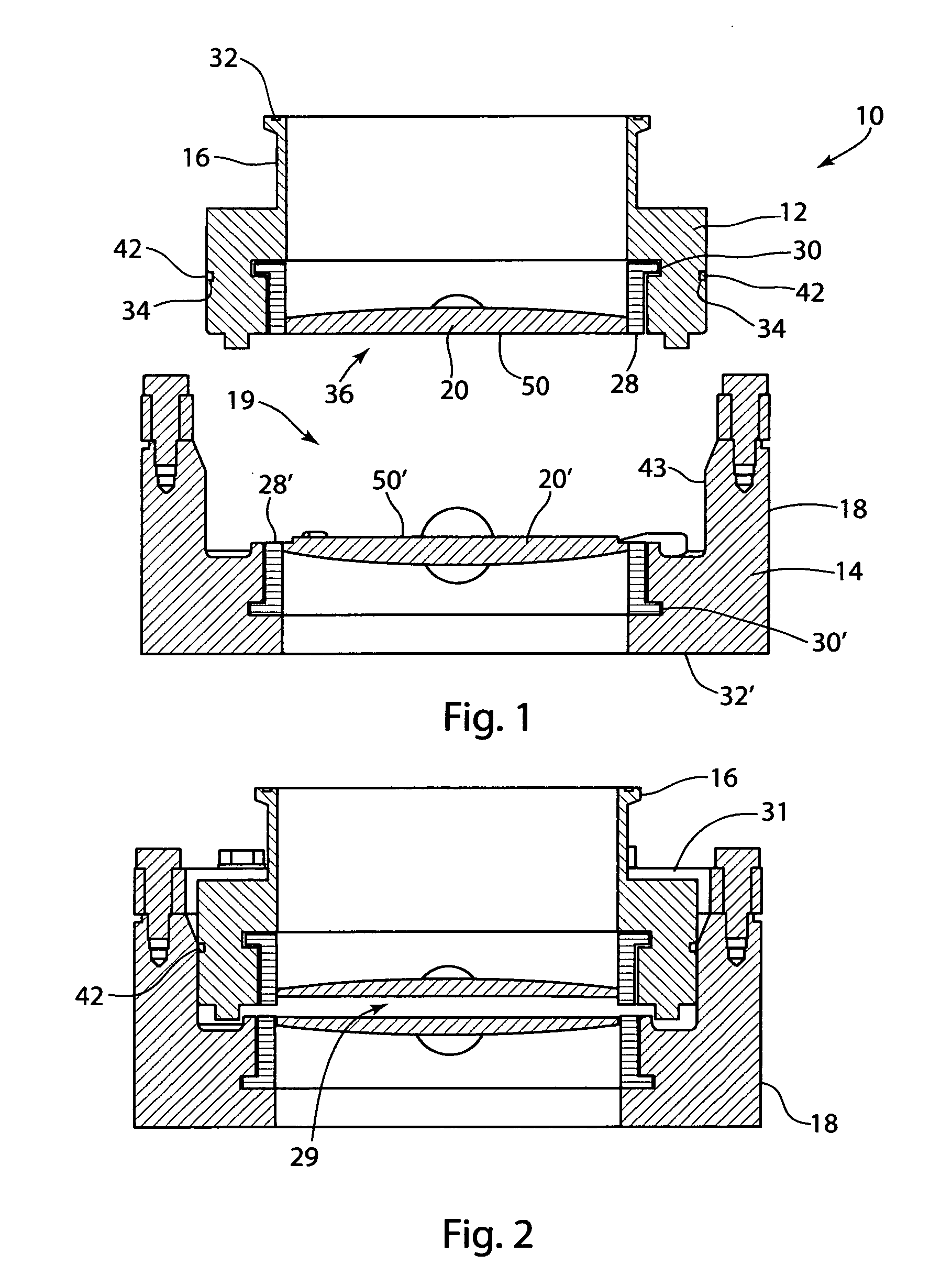
[0058]The valve closure member 20,20′ is engageable with and disengageable from an annular valve seat in the form of an annular seal 28,28′ which is seated in a complimentarily-shaped recess 30,30′ in the valve housing. The seal comprises a EPDM annular abutment portion (alternatively, perfluoroelastomer or any other suitable material can be used) which, in use, engages the valve closure member 20,20′.

[0059]As seen in FIGS. 1 to 3, the valve assembly comprises releasably securable valve port...


PUM

PropertyMeasurementUnit
temperaturesaaaaaaaaaa
circumferenceaaaaaaaaaa
displacementaaaaaaaaaa

Abstract

A valve assembly (10) comprising two valve portions, an upper and lower valve portion (12, 14), each having a valve housing indicated generally at (16, 18), a valve seat (28, 28′) and a valve closure member (20, 20′) moveable between a first position in which the valve closure member is displaced from the valve seat and the valve is open, and a second position in which the valve closure member cooperates with the valve seat and the valve is closed, wherein the assembly has a first configuration in which the first and second valve portions engage with one another, the valve closure members being closed, and the valve closure members being disposed at a distance apart defining, with the housing, a chamber (29) therebetween, which is capable of being sealed from the surrounding environment, having an inlet (44, 44′) and an outlet (45, 46′) through which sterilizing medium may pass, and a second configuration in which the valve closure members engage with one another and are moveable from their first to their second position, and a third configuration in which two valve portions are disengaged from one another.

Description

BACKGROUND OF THE INVENTION[0001]The present invention relates to valves, and in particular, but not exclusively, to valves for controlling, charging, discharging and / or regulating the flow of powders and / or fluids.[0002]Valves, such as split butterfly valves, are available in many designs and used widely for processes where product containment is required to prevent product exposure to environment and personnel working in close proximity of the product. The split valves are designed pre-dominantly for handling and contained transfer of solid state powders and granular material alike.[0003]Split valve design allows the valve to be split open into two halves, commonly called alpha and beta halves, or active and passive halves. The valve design is such that when split, the two halves keep the contents on either side sealed and contained.[0004]Similar to the split butterfly valve, a split ball valve can also be used for contained transfer of solids and more commonly liquids. Historical...

Claims


Application Information

Patent Timeline
Patent Type & Authority Patents(United States)
IPC IPC(8): F16L29/00F16K1/226F16K1/22F16K1/44F16K27/02
CPCF16K1/226F16K1/222F16K1/446F16K27/0218F16L29/00Y10T29/49407Y10T137/4259
Inventor RANPURIA, CHANDULAL KANTILAL
Owner CHARGEPOINT TECH
Why Eureka
Try Eureka