Method of manufacturing liquid ejection head

Inactive Publication Date: 2006-09-07
FUJIFILM CORP
View PDF7 Cites 3 Cited by
  • Summary
  • Abstract
  • Description
  • Claims
  • Application Information

AI Technical Summary

Benefits of technology

[0012] The present invention has been contrived in view of the aforementioned circumstances, an object thereof being to provide a method of manufacturing a liquid ejection head whereby manufacturing costs can be reduced, without irregularities in the thickness of the piezoelectric bodies.

Problems solved by technology

However, if the diaphragm is formed to a thin dimension, then the strength of the diaphragm declines so that it becomes difficult to form the piezoelectric bodies directly onto the diaphragm.
However, in the former method, it is necessary to repeat the step of division each time a print head is manufactured, and hence there is a risk that variation may occur in the shape of the piezoelectric bodies, and furthermore, an increase in manufacturing costs results.
Moreover, in the latter method, there is a risk that variation may occur in the thickness of the piezoelectric bodies.
Furthermore, if an epoxy resin or low-melting-point glass is used to bond together the piezoelectric material and the common electrode, as described in Japanese Patent Application Publication No. 7-171966, then there is no bonding stability, the electric field applied to the piezoelectric bodies declines because an insulating material is inserted between the piezoelectric bodies and the common electrode, and the displacement of the piezoelectric bodies falls.

Method used


Image

  • Method of manufacturing liquid ejection head
  • Method of manufacturing liquid ejection head
  • Method of manufacturing liquid ejection head

Examples


first embodiment

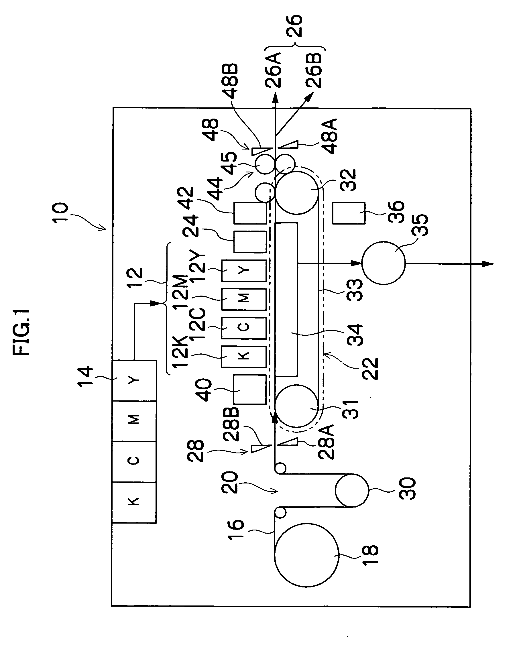
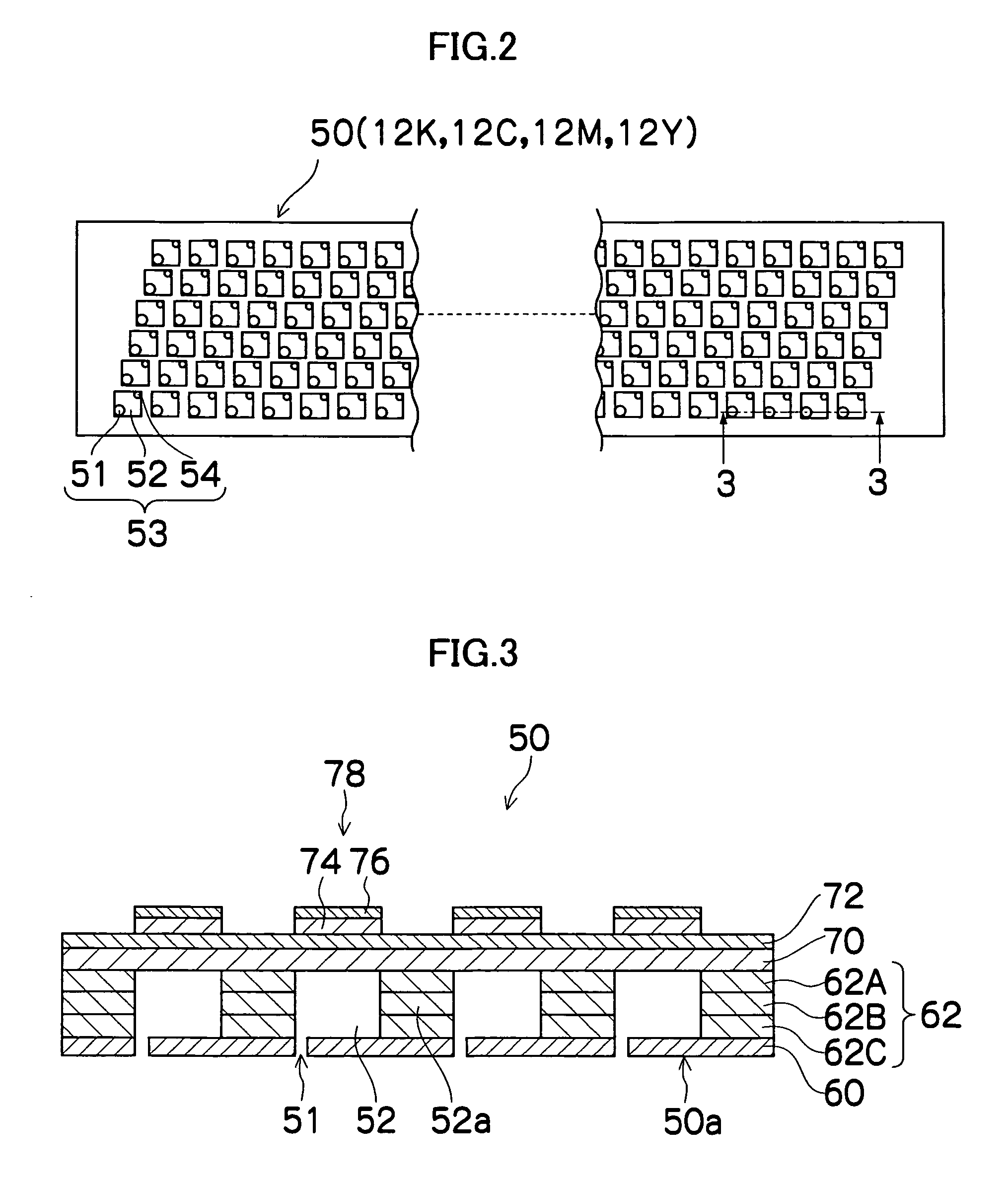
[0033]FIG. 1 is a general schematic drawing of an inkjet recording apparatus having a print head (liquid ejection head) to which an embodiment of the present invention is applied. As shown in FIG. 1, the inkjet recording apparatus 10 comprises: a print unit 12 having a plurality of print heads 12K, 12C, 12M, and 12Y for ink colors of black (K), cyan (C), magenta (M), and yellow (Y), respectively; an ink storing and loading unit 14 for storing inks of K, C, M and Y to be supplied to the print heads 12K, 12C, 12M, and 12Y; a paper supply unit 18 for supplying recording paper 16; a decurling unit 20 for removing curl in the recording paper 16 supplied from the paper supply unit 18; a suction belt conveyance unit 22 disposed facing the nozzle face (ink droplet ejection face) of the print unit 12, for conveying the recording paper 16 while keeping the recording paper 16 flat; a print determination unit 24 for reading the printed result produced by the print unit 12; and a paper output un...

second embodiment

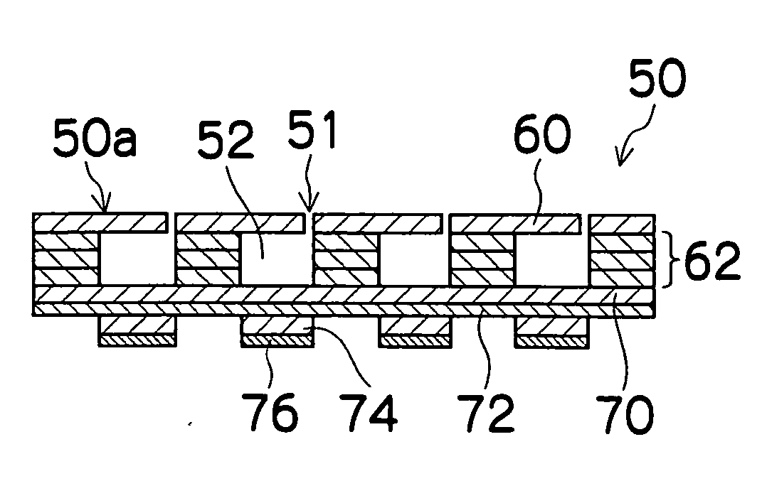
[0081] Next, a second embodiment of the present invention will be described. FIGS. 5A and 5B are illustrative diagrams showing a portion of steps for manufacturing the print head 50 according to the second embodiment. FIGS. 5A and 5B correspond respectively to FIGS. 4D and 4E in the first embodiment.

[0082] In the second embodiment, in contrast to the first embodiment, a binder resin 96 is filled into the recess sections 80a in the molding substrate 80, before filling the piezoelectric material 82 into same as shown in FIG. 5A. The material of the binder resin 96 is similar to the binder material used for the green sheet and printing paste, and an acrylic resin, polyurethane resin, nylon-type resin, teflon-type resin, silicone resin, or the like, is used. Similarly to the first embodiment, the green sheets 84 and 88 are arranged onto the molding substrate 80 so as to cover the recess sections 80a.

[0083] Next, in a binder removal step shown in FIG. 5B, the molding substrate 80 on wh...

third embodiment

[0084] Next, a third embodiment of the present invention will be described. FIG. 6 is an illustrative diagram showing a portion of steps for manufacturing the print head 50 according to the third embodiment, and corresponds to FIG. 4D in the first embodiment.

[0085] In the third embodiment, as shown in FIG. 6, the binder resin 96 and the individual electrodes 76 are filled into the recess sections 80a of the molding substrate 80 before filling the piezoelectric material 82, and the green sheets 84 and 88 are then arranged onto the molding substrate 80 so as to cover the recess sections 80a. The subsequent steps are similar to those in the first and second embodiments, with the exception of the step of forming the individual electrodes.

[0086] By filling the individual electrodes 76 together with the piezoelectric material 82, the individual electrodes 76 are calcined simultaneously with the green sheets 84 and 88 and the piezoelectric material 82 in the calcining step, and therefore...


PUM

PropertyMeasurementUnit
Temperatureaaaaaaaaaa

Abstract

The method manufactures a liquid ejection head in which piezoelectric bodies are formed on a diaphragm which constitutes walls of a plurality of pressure chambers. The method comprises the steps of: filling piezoelectric material into a plurality of recess sections of a molding substrate formed with the plurality of recess sections so as to correspond to the pressure chambers; then performing a lamination step of arranging a first green sheet that is to form the diaphragm onto the molding substrate in such a manner that the first green sheet covers the recess sections filled with the piezoelectric material; then performing a first heating step of heating the piezoelectric material filled in the recess sections; and then separating the piezoelectric material from the molding substrate.

Description

BACKGROUND OF THE INVENTION [0001] 1. Field of the Invention [0002] The present invention relates to a method of manufacturing a liquid ejection head, and more particularly, to a method of manufacturing a piezoelectric type liquid ejection head. [0003] 2. Description of the Related Art [0004] There are image forming apparatuses, such as inkjet printers, which employ a piezoelectric type print head (liquid ejection head) that uses the displacement of piezoelectric elements. As a structure for a piezoelectric element, for example, a common electrode is formed on the whole surface of a diaphragm which constitutes the upper surface of a plurality of pressure chambers, and piezoelectric bodies and individual electrodes are formed to overlap each other on the common electrode at positions corresponding to the pressure chambers. When a voltage is applied to a piezoelectric element, the piezoelectric body is displaced due to a lateral piezoelectric effect, and the volume of the pressure cha...

Claims


Application Information

Patent Timeline
IPC IPC(8): C04B33/32B28B1/00B32B37/00B41J2/045B41J2/055B41J2/135B41J2/14B41J2/145B41J2/16H01L41/09H01L41/187H01L41/22H01L41/333
CPCB41J2/161B41J2/1637B41J2002/14459Y10T29/4913Y10T29/42Y10T29/49401Y10T29/49128Y10T29/49126
Inventor MITA, TSUYOSHI
Owner FUJIFILM CORP
Why Eureka
Try Eureka