
Liner installation in pipes

Active Publication Date: 2006-09-07
MICHELS CORPORATION +2
View PDF47 Cites 17 Cited by
  • Summary
  • Abstract
  • Description
  • Claims
  • Application Information

AI Technical Summary

Benefits of technology

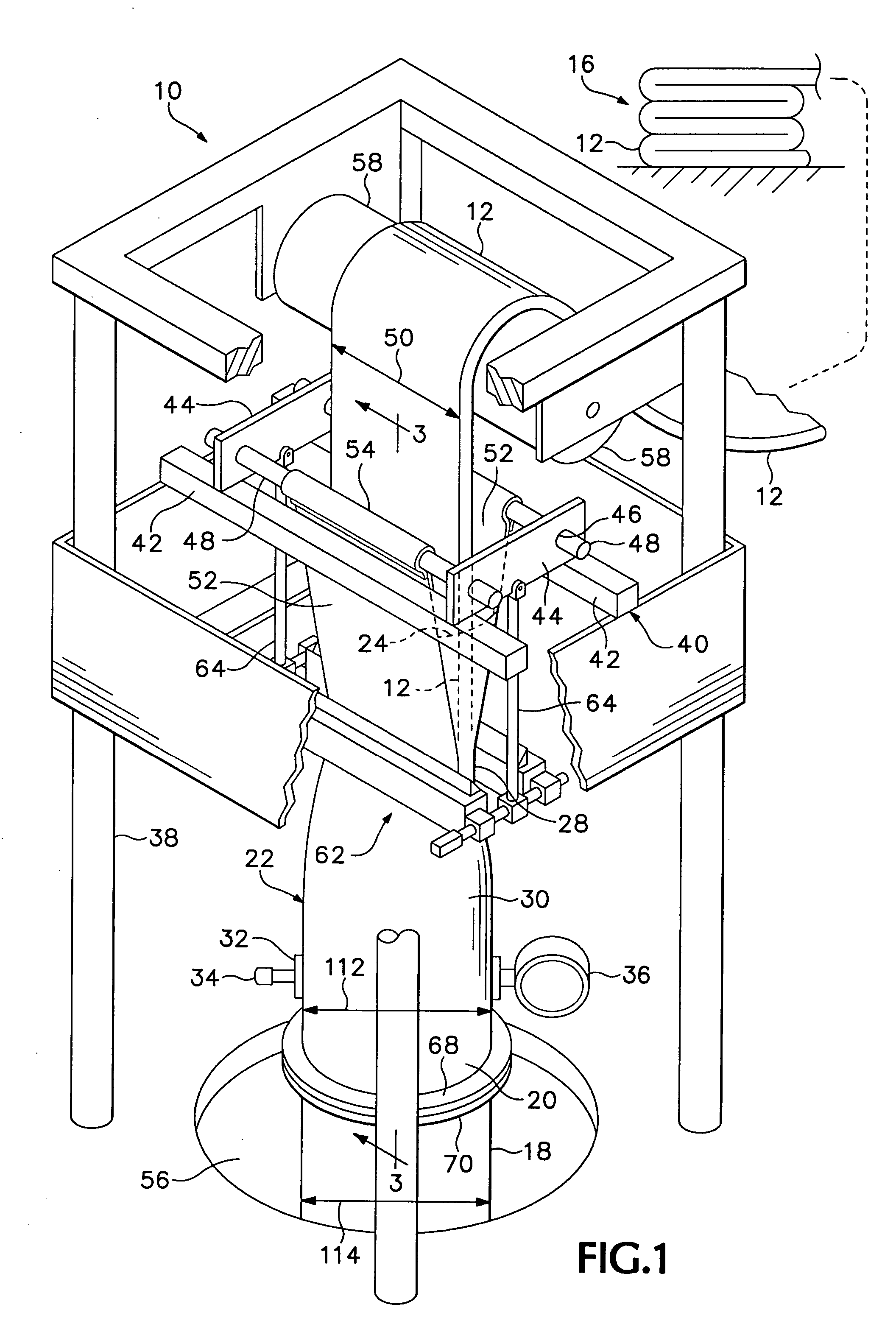
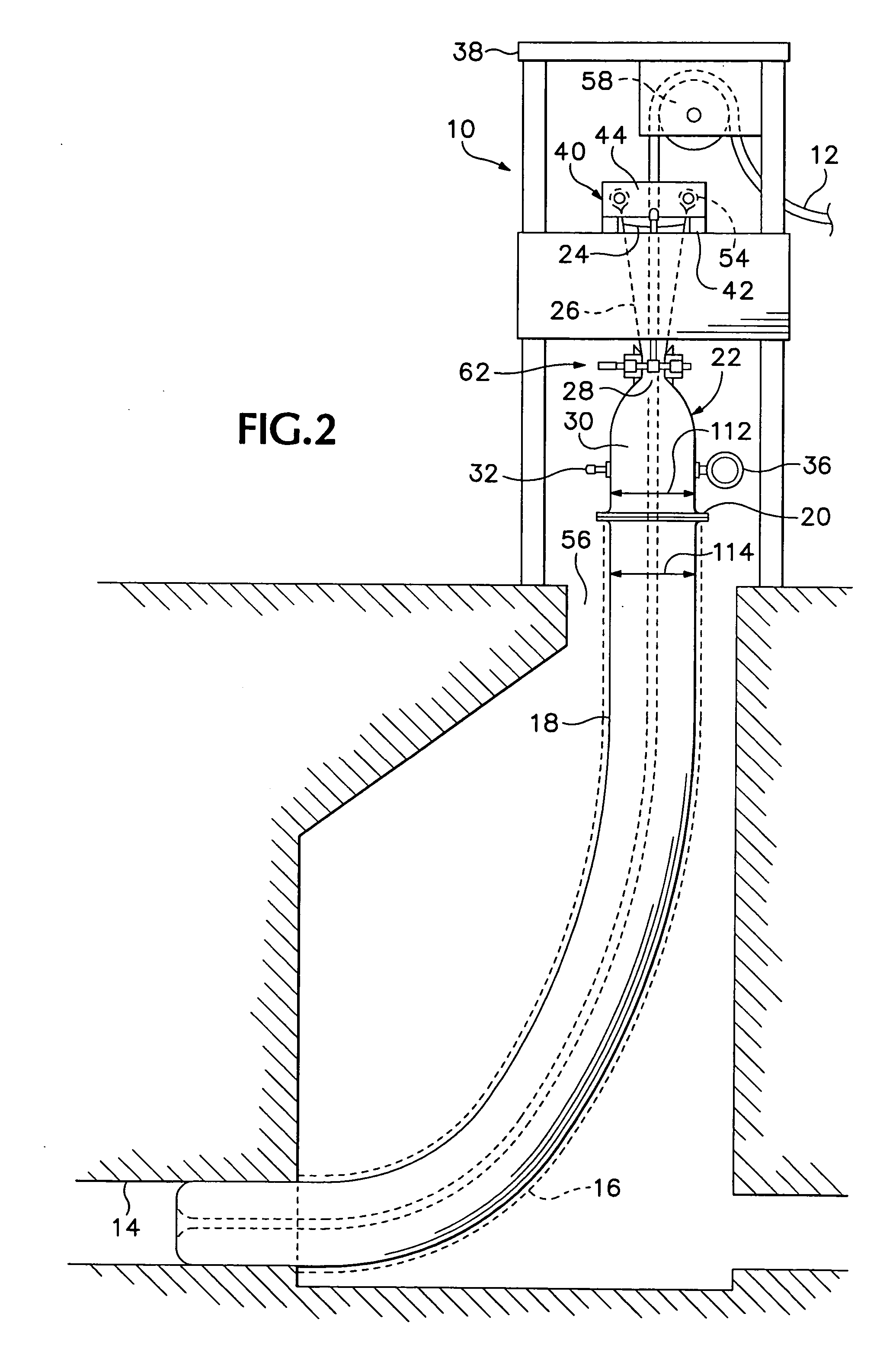
[0007] The present invention supplies an answer to the aforementioned need for a relatively small and inexpensive apparatus and a method for its use in installing a flexible tubular liner in a tubular vessel. A feeder of flexible material may be attached to or manufactured integrally with a length of a flexible tubular liner, and includes a mouth leading to a throat for receiving and conducting a liner in the form of a flat-folded, flexible inside-out tube into an adjacent flexible pressure-containing section from which such a tubular liner can be extended and inverted into position for use to repair or line a pipe. The pressure-containing section acts to hold air or another fluid under pressure to act on the flexible tubular liner. The feeder can be supported by a simple support structure where the liner is to be installed.
[0008] A throat supporting mechanism is provided to shape and support the throat around the flexible tubular liner, in such a way as to allow the liner to enter the flexible feeder longitudinally through the throat in a flattened, folded, inside-out configuration without excessive loss of pressure from the pressure-containing section, so that the pressure of the fluid in the feeder and in an adjacent portion of the tubular liner can be used to extend and invert the tubular liner into the required position within a pipe.

Problems solved by technology

Underground pipes are used as conduits for sewage or water supplies and may begin to leak after time as a result of ground movement, nearby construction, erosion, or other factors.
Previously, large, heavy and unwieldy containers have been used to retain and control fluid under pressure to urge the liner, originally in an inside-out condition, to extend along and through a length of underground pipe to be repaired by installation of the liner, and invert itself progressively in a required position.
Such apparatus has been undesirably unwieldy and expensive, particularly for repair of large-diameter sewer pipes.

Method used


Image

  • Liner installation in pipes
  • Liner installation in pipes
  • Liner installation in pipes

Examples


Embodiment Construction

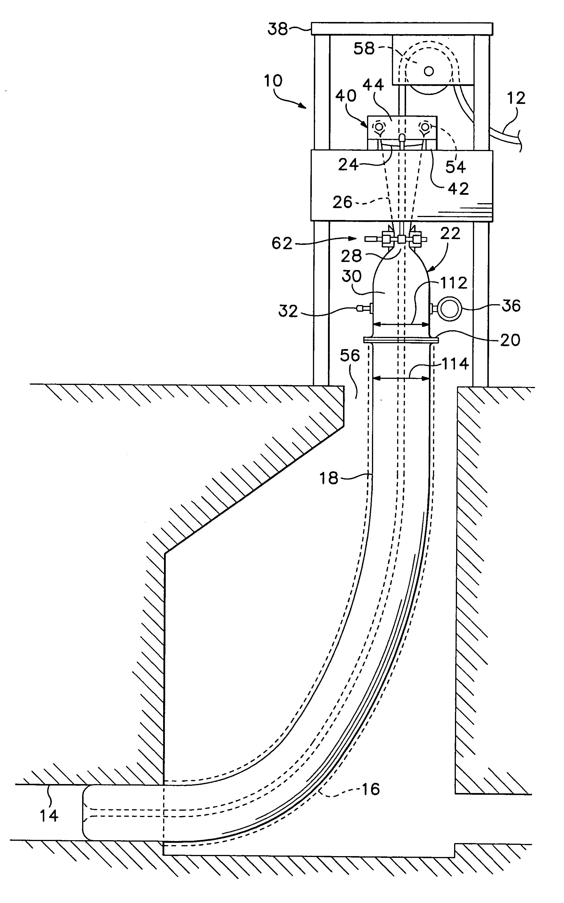
[0016] Referring now to the drawings which form a part of the disclosure herein, in FIGS. 1 and 2 a liner installation apparatus 10 is used to install a liner 12 into a pipe or other tubular vessel such as a sewer pipe 14, from a supply such as a stack 16 of tubular liner material which has been prepared for installation, as by being impregnated with a quantity of an uncured resin, and by being placed into a flattened, folded, inside-out configuration arranged for progressive easy removal from the stack 16. Typically the liner 12 is folded flat, and it may be folded double in readiness for inversion, as shown, for example, in FIG. 19 of Waring et al. U.S. Pat. No. 6,390,795. The liner is of a size to fit snugly inside the pipe into which it is to be installed.

[0017] A near-end portion 18 of the liner 12 has been inverted and pulled back along the inside-out liner 12 into a right-side-out configuration as shown in FIG. 1. The near-end portion 18 is connected to an outfeed end 20 of ...


PUM

PropertyMeasurementUnit
Pressureaaaaaaaaaa
Flow rateaaaaaaaaaa
Diameteraaaaaaaaaa

Abstract

Apparatus and a method for installing a tubular liner in a pipe, as in repair of underground sewer piping. A feeder is of flexible material, which may be similar to that of which the tubular liner is made, and is connected to an end of the tubular liner. The feeder includes a throat portion through which a quantity of inside-out tubular liner is drawn into the feeder by fluid pressure within the feeder and beyond the throat, and the tubular liner is thence urged by fluid pressure into the pipe where it is to be installed.

Description

[0001] The present invention relates to apparatus and a method for feeding and inverting a flexible tubular liner into the interior of a hollow tubular vessel, such as a previously existing underground sewer pipe. [0002] Underground pipes are used as conduits for sewage or water supplies and may begin to leak after time as a result of ground movement, nearby construction, erosion, or other factors. It is well known to repair underground pipes by using fluid pressure to invert a flexible liner into the pipe, where the liners can be secured by chemically hardening resin with which the liner is impregnated before being installed. Previously, large, heavy and unwieldy containers have been used to retain and control fluid under pressure to urge the liner, originally in an inside-out condition, to extend along and through a length of underground pipe to be repaired by installation of the liner, and invert itself progressively in a required position. As used herein the term pipe is meant t...

Claims


Application Information

Patent Timeline
IPC IPC(8): B29C63/20
CPCB29C63/36F16L55/1651
Inventor WARING, STEPHEN T.
Owner MICHELS CORPORATION
Learn More