Eureka AIR delivers breakthrough ideas for toughest innovation challenges, trusted by R&D personnel around the world.

Film-bulk acoustic wave resonator with motion plate

Active Publication Date: 2006-09-07
AVAGO TECH INT SALES PTE LTD
View PDF99 Cites 67 Cited by
  • Summary
  • Abstract
  • Description
  • Claims
  • Application Information

AI Technical Summary

Problems solved by technology

One disadvantage to capacitive pressure sensors with this configuration is the low resonant frequency at which the oscillator circuit operates.
Another disadvantage to the capacitive pressure sensors with this configuration is that the manufacture of the sensor capacitor and the oscillator circuit is often complex.
Yet another disadvantage to the prior art capacitive pressure sensors is that the size of the resulting sensor capacitor and the oscillator circuit is often bulky and space inefficient.
Consequently, these prior art capacitive pressure sensors may not meet the stringent size and space requirements of portable or other compact applications.

Method used


Image

  • Film-bulk acoustic wave resonator with motion plate
  • Film-bulk acoustic wave resonator with motion plate
  • Film-bulk acoustic wave resonator with motion plate

Examples


Embodiment Construction

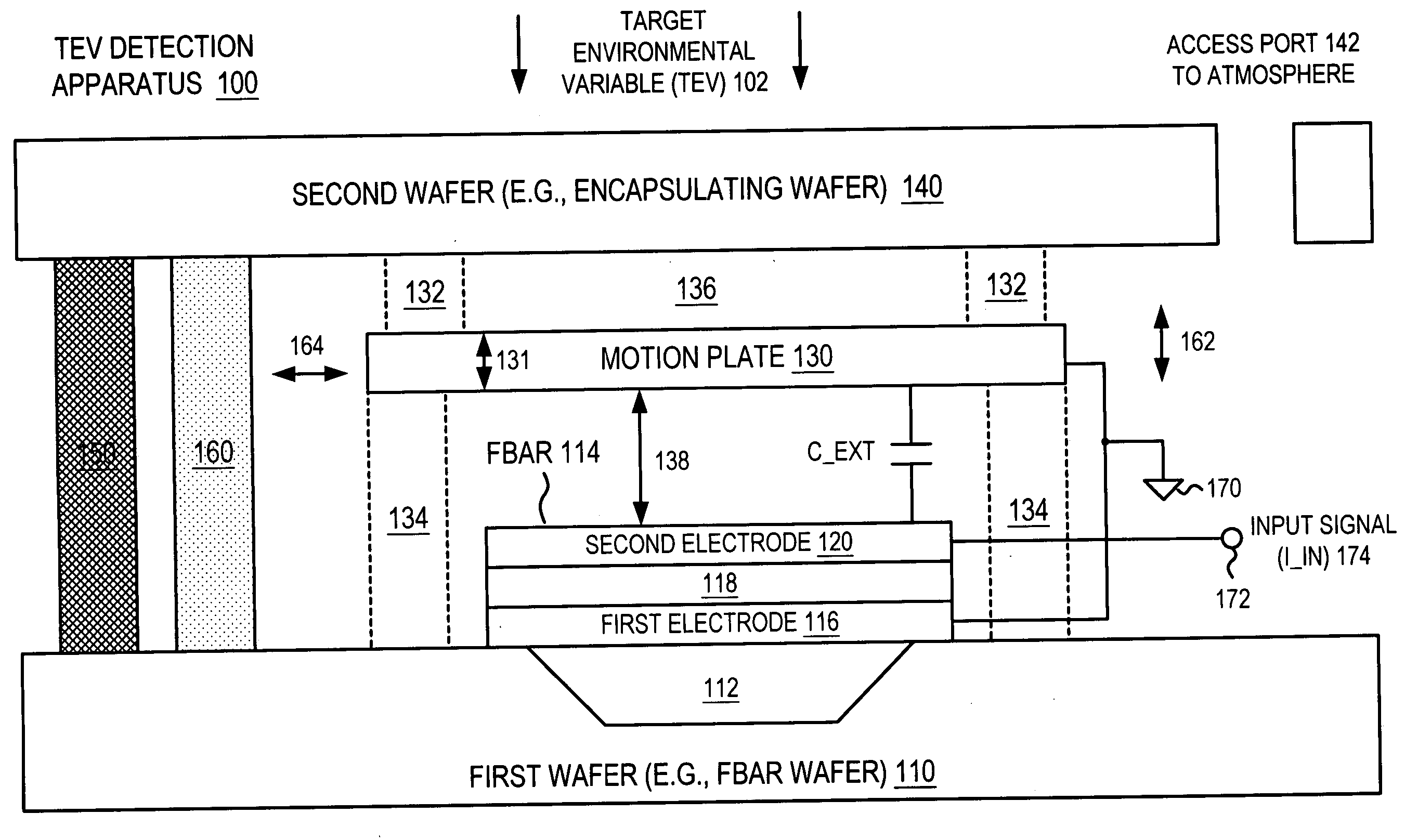
[0021] A film-bulk acoustic wave resonator (FBAR) with motion plate is described. In the following description, for the purposes of explanation, numerous specific details are set forth in order to provide a thorough understanding of the present invention. It will be apparent, however, to one skilled in the art that the present invention may be practiced without these specific details. In other instances, well-known structures and devices are shown in block diagram form in order to avoid unnecessarily obscuring the present invention.

[0022] Target Environment Variable (TEV) Detection Apparatus 100

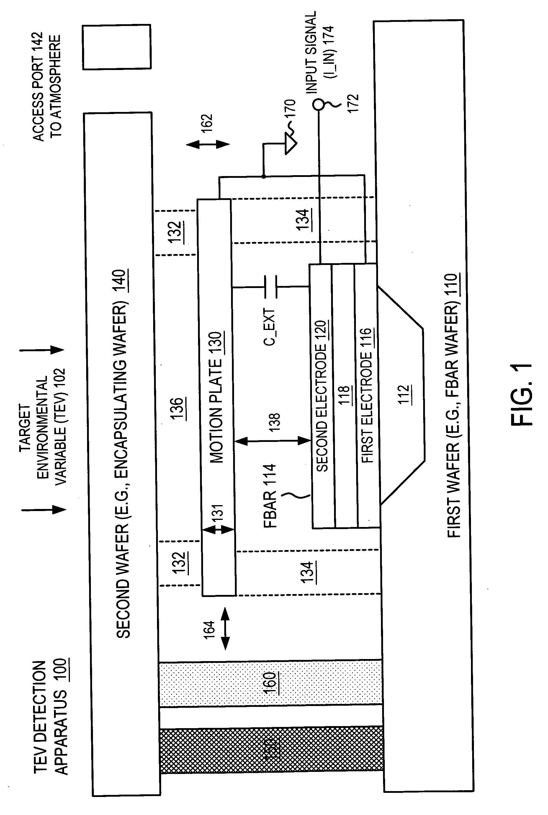
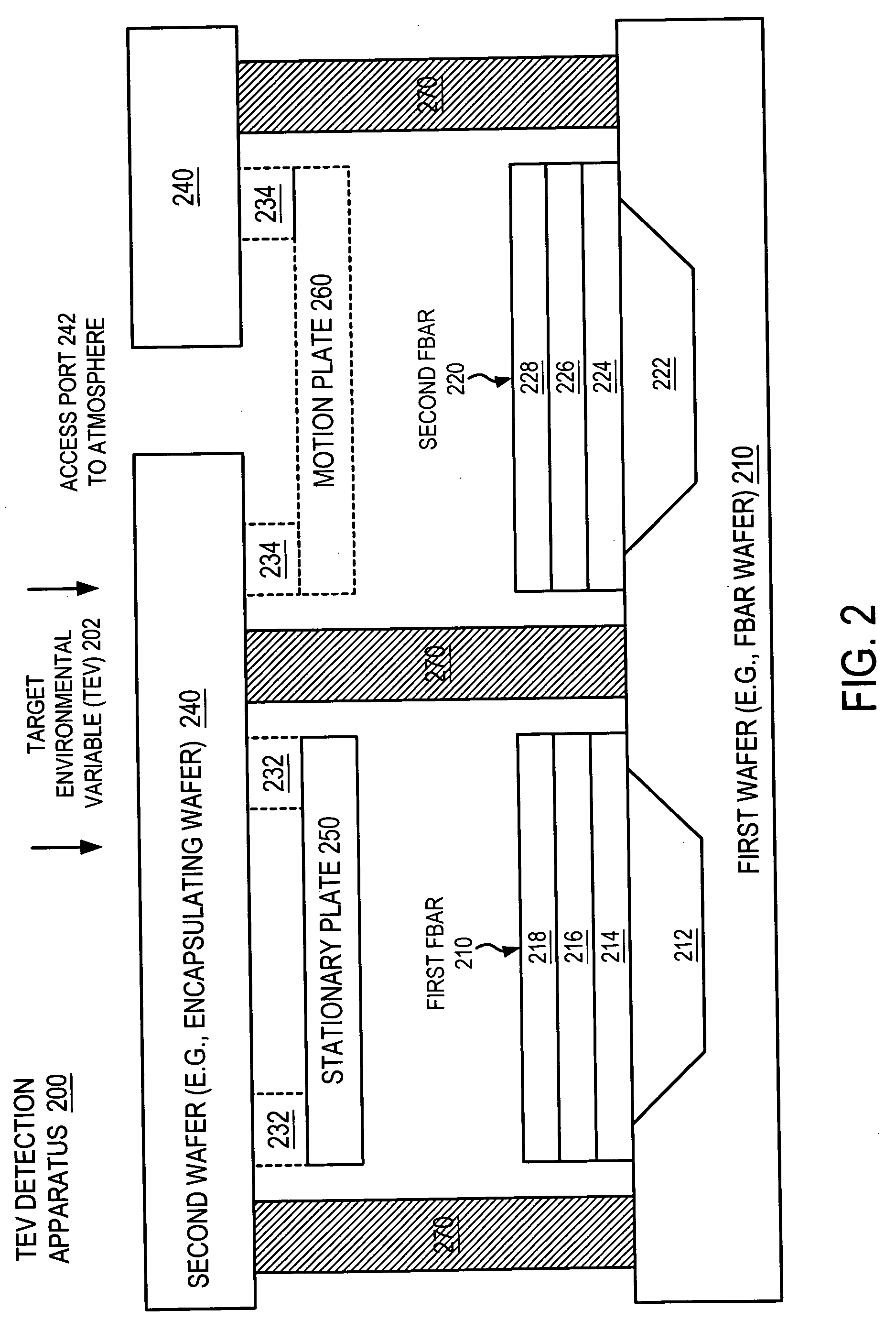
[0023]FIG. 1 illustrates a target environment variable (TEV) detection apparatus 100 that utilizes a film-bulk acoustic wave resonator (FBAR) 114 with a motion plate 130 according to one embodiment of the invention. The TEV detection apparatus 100 senses, detects or measures at least one target environmental variable (TEV) 102, which can be, for example, pressure, acceleration, sound, or vib...


PUM


Abstract

An apparatus and method for measuring a target environmental variable (TEV) that employs a film-bulk acoustic resonator with motion plate. The film-bulk acoustic resonator (FBAR) includes an acoustic reflector formed in an FBAR wafer and a surface. A first electrode is formed on the surface of the acoustic reflector and has a surface. A piezoelectric layer is formed on the surface of the first electrode and has a surface. A second electrode is formed on the surface of the piezoelectric layer. A motion plate is suspended in space at a predetermined distance relative to the surface of the second electrode and is capacitively coupled to the FBAR.

Description

BACKGROUND OF THE INVENTION [0001] Capacitive pressure sensors are well known in the prior art. A typical pressure sensor includes a fixed element with a rigid, planar conductive surface that forms one plate of a substantially parallel plate capacitor. A displaceable (relative to the fixed element) conductive member, such as a metal diaphragm, or a plated non-conductive member, such as a metallized ceramic diaphragm, forms the other plate of the capacitor. [0002] The diaphragm is edge-supported so that a central portion is substantially parallel to and opposite the fixed plate. Because the sensor generally has the form of a parallel plate capacitor, the characteristic capacitance C of the sensor may be approximated by the equation: C=(ε*A) / d, where epsilon (ε) is the permittivity of the material between the parallel plates, A is the surface area of the parallel plate, and d represents the gap between the plates. It is noted that the characteristic capacitance is inversely proportion...

Claims


Application Information

Patent Timeline
IPC IPC(8): H01L41/04
CPCG01L1/165G01P15/097H03H3/02H03H9/02007H03H9/171
Inventor HOEN, STORRS T.UNKRICH, MARK A.TRUTNA, WILLIAM R.LARSON, JOHN D. IIIRUBY, RICHARD C.FLOWER, GRAHAM M.GROT, ANNETTE
Owner AVAGO TECH INT SALES PTE LTD
Why Eureka
Eureka Blog
Learn More