Liquid crystal display device

a liquid crystal display and vertical alignment technology, applied in optics, non-linear optics, instruments, etc., can solve the problems of insufficient viewing angle characteristics of tn mode liquid crystal display devices, extreme deterioration of tone and contrast, orientations respectively, etc., and achieve the effect of substantial aperture ratio and better display quality

Active Publication Date: 2006-07-06
SHARP KK
View PDF10 Cites 180 Cited by
  • Summary
  • Abstract
  • Description
  • Claims
  • Application Information

AI Technical Summary

Benefits of technology

[0027] With the aforementioned matters taken into consideration, an object of the present invention is to provide a MVA mode liquid crystal display device whose substantial aperture ratio is higher so as to be applicable to a notebook personal computer, and which is better at the display quality even when viewed in an oblique direction.

Problems solved by technology

However, the TN mode liquid crystal display device has a disadvantage of having insufficient viewing angle characteristics.
In other words, with regard to the TN mode liquid crystal display device, tone and contrast are extremely deteriorated when the liquid crystal panel is viewed in an oblique direction.
Although, however, the IPS mode liquid crystal display device is good at viewing angle characteristics, the orientations respectively of the liquid crystal molecules above the picture element electrode and the common electrode cannot be controlled since voltage is applied in a direction which is parallel with the substrate.
This brings about a disadvantage that the IPS mode liquid crystal display device substantially has a low aperture ratio, and that the screen of it is dark if a powerful backlight were not used.
As a result, this kind of MVA mode liquid crystal display device has hardly been adopted for a notebook personal computer, which requires power consumption to be low.
This brings about a problem that the response time is long.
For this reason, the conventional MVA mode liquid crystal display device has a disadvantage that the display quality is deteriorated when viewed in an oblique direction although a preferable display quality can be obtained when viewed from the front.
For this reason, a phenomenon occurs in which an image to be viewed in the oblique direction looks whitish (washes out) in comparison with that to be viewed from the front, thus deteriorating the display quality.
This causes optical characteristics of the picture element to be irregular, thus constituting a cause of display unevenness.

Method used


Image

  • Liquid crystal display device
  • Liquid crystal display device
  • Liquid crystal display device

Examples


first embodiment

[0083]FIG. 3 is a plan view of a liquid crystal display device according to a first embodiment of the present invention. FIG. 4 is a cross-sectional schematic view of the liquid crystal display device according to the first embodiment. Incidentally, FIG. 3 shows two picture element regions.

[0084] As shown in FIG. 4, a liquid crystal panel 100 is constituted of: a TFT substrate 110; an opposing substrate 130; and a liquid crystal layer 140, made of liquid crystal with negative dielectric anisotropy, which is contained in the space between the TFT substrate 110 and the opposing substrate 130. Polarizing plates 141a and 141b are arranged respectively on the two sides in the thickness direction of this liquid crystal panel 100. The liquid crystal layer 140 includes a polymer which has been formed in the following process. Polymer components (monomer or oligomer) are added to the liquid crystal, and beams of ultraviolet light are irradiated to the polymer components. Thereby, the polyme...

second embodiment

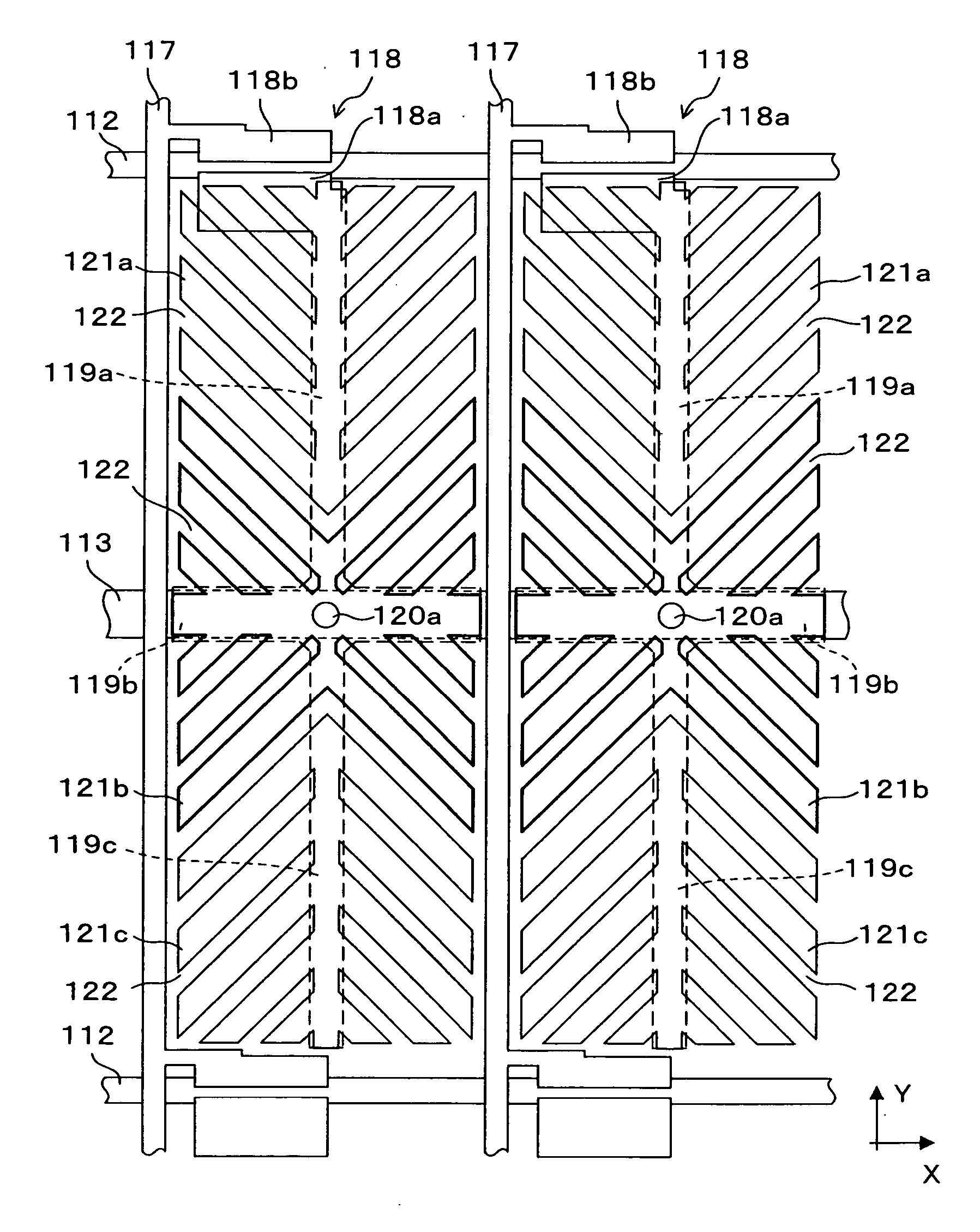
[0122]FIG. 6 is a plan view showing a liquid crystal display device according to a second embodiment of the present invention. Incidentally, if components and equivalents in FIG. 6 were the same as, or similar to, those in FIG. 3, the components and equivalents in FIG. 6 are denoted by the same reference numerals and symbols as those in FIG. 3 are. Thus, detailed descriptions will be omitted for the same, or similar components and equivalents in FIG. 6.

[0123] In the case of this embodiment, two sub picture element electrodes 152a and 152b are formed in a single picture element region. The sub picture element electrodes 152a (directly-connected picture element electrode) is arranged in a range upper in the Y axis direction in each of the picture element regions. The sub picture element electrode 152a is divided into four fields (domain control fields) by the center line in parallel with the X axis and the center line in parallel with the Y axis. A plurality of slits 153 extending in...

third embodiment

[0132]FIG. 7 is a plan view showing a liquid crystal display device according to a third embodiment of the present invention. If components and equivalents in FIG. 7 were the same as, or similar to, those in FIG. 3, the components and equivalents in FIG. 7 are denoted by the same reference numerals and symbols as those in FIG. 3 are. Thus, detailed descriptions will be omitted for the same, or similar, components and equivalents in FIG. 7.

[0133] In the case of this embodiment, too, two sub picture element electrodes 162a and 162b are formed in a single picture element region. The sub picture element electrode 162a (directly-connected picture element electrode) is arranged in a range upper in the Y axis direction in each of the picture element regions. The sub picture element electrode 162a is divided into four fields (domain control fields) by the center line in parallel with the X axis and the center line in parallel with the Y axis. A plurality of slits 163 extending in a directi...


PUM

PropertyMeasurementUnit
angleaaaaaaaaaa
angleaaaaaaaaaa
angleaaaaaaaaaa

Abstract

A liquid crystal display device according to the present invention is constituted of a TFT substrate and an opposing substrate which are arranged so as to be opposite to each other with a liquid crystal layer interposed therebetween. In addition, in the liquid crystal layer, formed is a polymer into which a polymer component added to liquid crystal is polymerized, and which determines directions in which liquid crystal molecules tilt when voltage is applied. In the TFT substrate, formed are a sub picture element electrode directly connected to a TFT and a sub picture element electrode connected to the TFT through capacitive coupling. In each of these sub picture element electrodes, formed are slits extending in directions respectively at angles of 45 degrees, 135 degrees, 225 degrees and 315 degrees to the X axis.

Description

CROSS-REFERENCE TO RELATED APLICATIONS [0001] This application is based upon and claims priority of Japanese Patent Application No. 2005-001356, filed on Jan. 6, 2005, the contents being incorporated herein by reference. BACKGROUND OF THE INVENTION [0002] 1. Field of the Invention [0003] The present invention relates to a MVA (Multi-domain Vertical Alignment) mode liquid crystal display device, and particularly to a liquid crystal display device in which a polymer for determining a direction in which liquid crystal molecules tilt while voltage is being applied is formed in a liquid crystal layer thereof. [0004] 2. Description of the Prior Art [0005] In general, a liquid crystal display device is constituted of: a liquid crystal panel which is fabricated to contain liquid crystal between two substrates thereof; and polarizing plates which are arranged respectively in the two sides of the liquid crystal panel. A picture element electrode is formed in each of picture elements in one su...

Claims


Application Information

Patent Timeline
Patent Type & Authority Applications(United States)
IPC IPC(8): G02F1/1343
CPCG02F1/133707G02F1/1393G02F2001/133757G02F2001/134345G02F1/136286G02F1/1334G02F1/133512G02F1/133514G02F1/134309G02F1/134336G02F1/133711G02F1/133761G02F1/133757G02F1/134345G02F1/1343
Inventor NAKANISHI, YOHEITASHIRO, KUNIHIROOHMURO, KATSUFUMIHANAOKA, KAZUTAKAHIROSAWA, JINSUGIURA, NORIOKANII, KENGOMAKIMOTO, SHOTAKONDO, NAOTOTSUSHIMA, ISAOTANOSE, TOMONORITAKAGI, TAKASHIFUJIKAWA, TETSUYA
Owner SHARP KK
Why Eureka
Try Eureka