MRI Compatible Implanted Electronic Medical Device

a technology of electronic medical devices and magnetic resonance scanners, applied in the field of implantable electronic medical devices, can solve the problems of affecting the imaging performance of magnetic resonance scanners, adversely affecting patient safety, and degrading the scanner performan

Inactive Publication Date: 2007-05-10
KENERGY INC
View PDF28 Cites 191 Cited by
  • Summary
  • Abstract
  • Description
  • Claims
  • Application Information

AI Technical Summary

Benefits of technology

[0024] The present implantable electronic medical device is compatible with magnetic resonance imaging and specifically with direct current (DC) magnetic fields, gradient magnetic fields, and RF fiel...

Problems solved by technology

First, incompatible implant components induce susceptibility difference, which destroys DC magnetic field homogeneity, thereby affecting the imaging performance of the magnetic resonance scanner.
Second, conductive materials present an opportunity for eddy currents to form, which currents generate heat that adversely affects patient safety and degrade the scanner performance by field distortion.
Third, the MRI fields may ruin the implanted device.
Fourth, the incompatible implant material can potentially cause serious internal injuries to the patient.
Obviously the surrounding tissue adjacent the implantable device will be damaged in this case, and the health of the patient will be compromised.
In addition, metallic components can become hot and burn the patient.
Due to MRI field induced torque and movement of the implant, its components may become disconnected making the device inoperable.
Ferrites and other ferromagnetic material in transformer cores, inductors and other electronic components become saturated, thereby jeopardizing the function of the medical device.
Heating causes electronic components to operate out of specification.
The homogeneity of the magnetic resonance imager's DC magnetic field will be distorted, destroying spectral resolution and geometric uniformity of the image.
The inhomogeneous field also results in rapid de-phasing of the signal inside the excited volume of the patient.
Even if the implanted device does not contain any fe...

Method used


Image

  • MRI Compatible Implanted Electronic Medical Device
  • MRI Compatible Implanted Electronic Medical Device
  • MRI Compatible Implanted Electronic Medical Device

Examples


Embodiment Construction

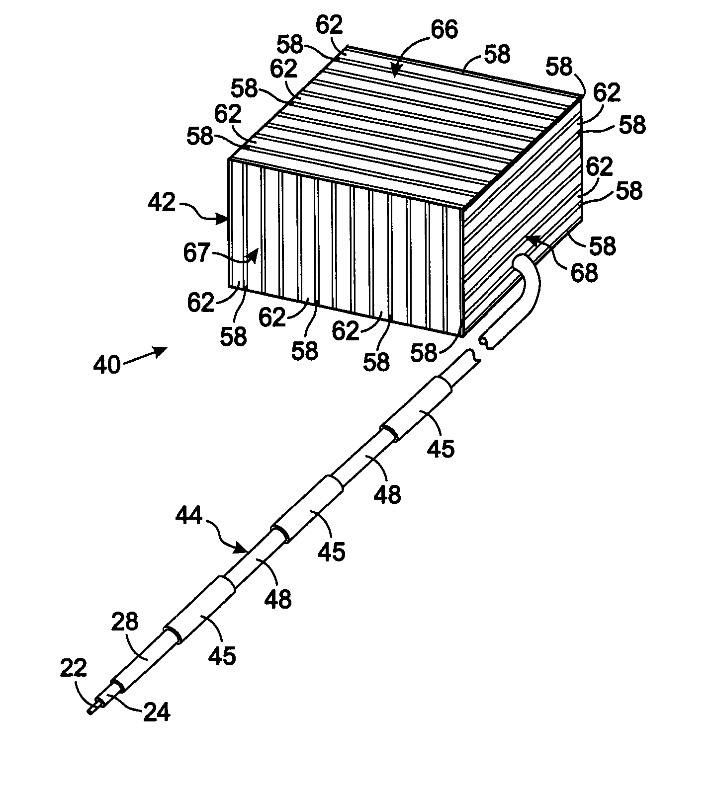
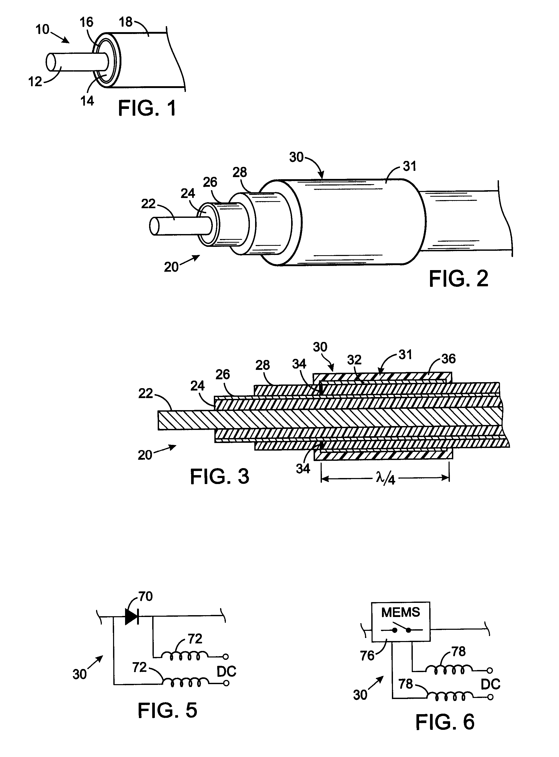
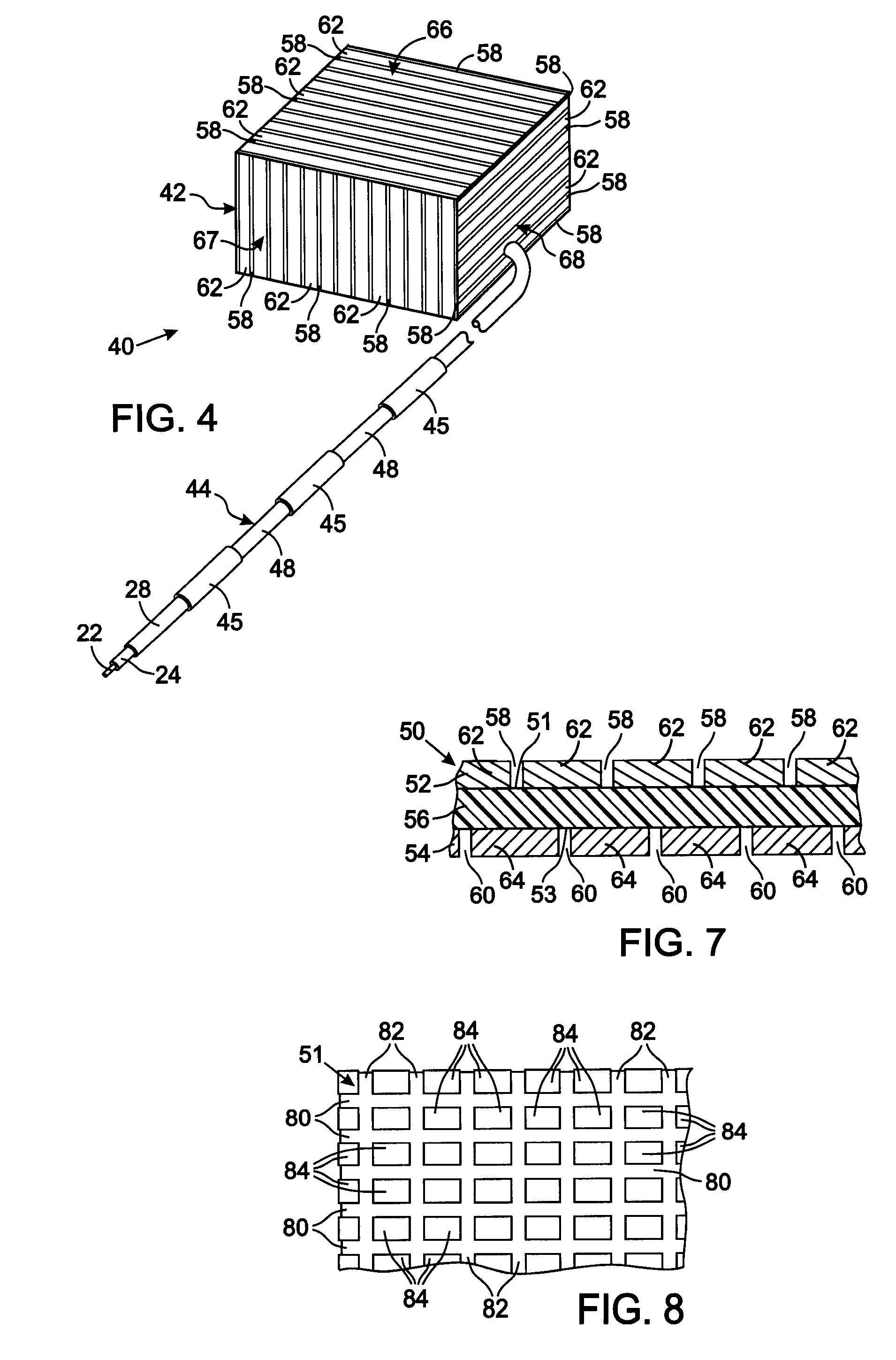
[0036] The present technique for MR compatibility of an implanted electronic medical device considers several effects of direct current (DC) magnetic fields, gradient magnetic fields, and RF fields on patient safety, the implanted device and the MRI scanner. As a consequence, the medical device incorporates one or more mechanisms that offer high impedance to currents induced by the MRI electromagnetic fields or prevent such currents from forming in the first place. These mechanisms comprise non-ferromagnetic components which have a magnetic susceptibility close to that of the surrounding tissue; electrical leads with traps for MRI induced currents, and a housing formed by a plurality of electrically conductive segments that combine to provide RF shielding of internal circuit while not providing large enough areas for formation of eddy currents. As used herein, a “trap” is a circuit element that either or blocks current induced by the MRI fields or significantly attenuates that curre...


PUM


Abstract

An implantable electronic medical device is compatible with a magnetic resonance imaging (MRI) scanner. The device has a housing with exterior walls, each formed by a dielectric substrate with electrically conductive layers on interior and exterior surfaces. A series of slots divide each layer into segments. Segmenting the layers provides high impedance to eddy currents produced by fields of the MRI scanner, while capacitive coupling of the segments provides radio frequency shielding for components inside the housing. Electrical leads extending from the housing have a pair of coaxially arranged conductors and traps that attenuate currents induced in the conductors by the fields of the MRI scanner.

Description

CROSS-REFERENCE TO RELATED APPLICATIONS [0001] This application claims benefit of U.S. Provisional Patent Application No. 60 / 734,018 filed Nov. 4, 2005.STATEMENT REGARDING FEDERALLY SPONSORED RESEARCH OR DEVELOPMENT [0002] Not Applicable BACKGROUND OF THE INVENTION [0003] 1. Field of the Invention [0004] The present invention relates implantable electronic medical devices, such as cardiac pacemakers and defibrillators for example, for stimulating tissue of animal for the therapeutic purposes, and such implantable medical devices that are compatible with magnetic resonance imaging (MRI). [0005] 2. Description of the Related Art [0006] Numerous medical conditions, such a cardiac and neurological dysfunctions, are treated by an implanted electronic device which provides electrical stimulation to the affected tissue of the animal. These devices have a plurality of metal components, including the outer case and wire leads extending from the case to electrodes in contact with the tissue t...

Claims


Application Information

Patent Timeline
IPC IPC(8): A61N1/00
CPCA61N1/3718A61N2001/086A61N1/375A61N1/086A61N1/37512
Inventor DENKER, STEPHENBEUTLER, ARTHUR J.BULKES, CHERIK
Owner KENERGY INC
Why Eureka
Try Eureka