Capacitive Position Sensor

a capacitive position and sensor technology, applied in the field of capacitive position sensors, can solve the problems of display screen, display screen, display screen,

Active Publication Date: 2010-02-25
NEODRON LTD +1
View PDF29 Cites 180 Cited by
  • Summary
  • Abstract
  • Description
  • Claims
  • Application Information

AI Technical Summary

Benefits of technology

[0015]In one embodiment, for each drive electrode there is one set of sense electrode branches providing co-extending portions that occupy a region in between adjacent sense electrodes in the first direction. Providing sense electrode branches allow a sensor to be made which has a greater extent in the first direction for a given number of sense channels.
[0016]In other embodiments, for each drive electrode there are multiple sets of sense electrode branches that are offset from each other in the second direction, the multiple sets providing respective co-extending portions extending over different respective regions in the first direction. Increasing the number of sense electrode branches per drive electrode allows a sensor to be made which has ever greater extent in the first direction without having to increase the number of sense channels.

Problems solved by technology

However, the methods described above increase the size and thickness, and may decrease the resolution of a device incorporating a display screen with a 2DCT sensor when it is more fashionable and desirable to produce smaller devices.
Furthermore, additional steps are required during manufacture and as a result there is an increased cost due to further components being needed.
However, this means that the number of connections required from the control circuits is increased which in turn results in more expensive control circuits and increased acquisition times, since the acquisition of signals from each of the sensing areas typically needs to be carried out at least partially in series, since not all sensing areas can be polled simultaneously owing to restrictions on the number of drive and sense lines, and controller channels, i.e. chip pins.
However, the method described above is only suitable for the drive electrodes and is not transferable to the sense electrodes.

Method used


Image

  • Capacitive Position Sensor
  • Capacitive Position Sensor
  • Capacitive Position Sensor

Examples


Embodiment Construction

[0074]Described herein is a two-electrode layer construction for a capacitive touch screen or 2DCT sensor.

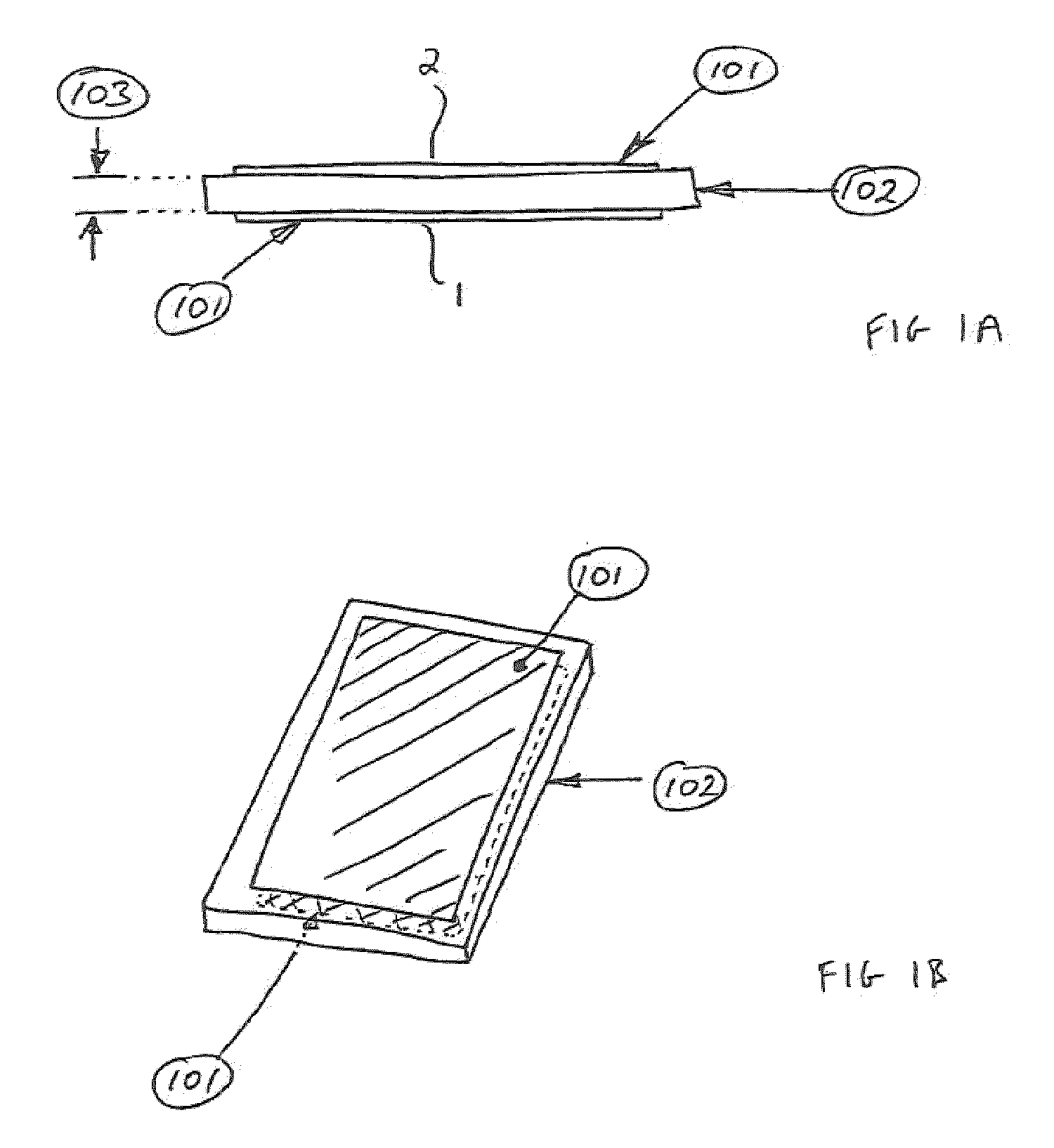
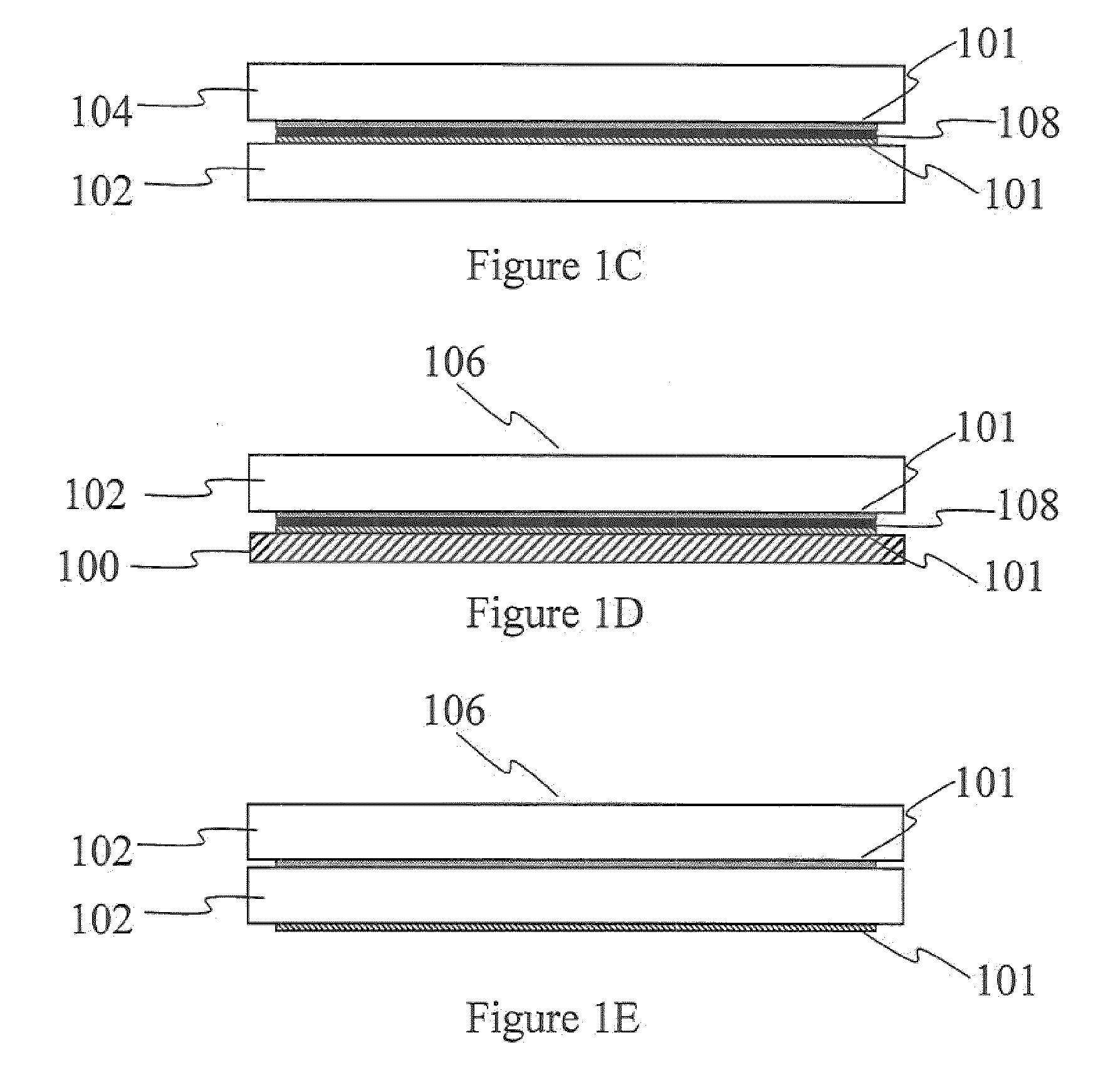
[0075]FIGS. 1A and 1B are schematic drawings in side view and perspective view of a two-electrode layer construction for a capacitive touch screen or 2DCT sensor. The layers 101 can generally be made of any conductive material and the layers can be arranged to oppose each other on two sides of any isolating substrate 102 such as glass, PET, FR4 etc. The thickness of the substrate 103 is non critical. Thinner substrates lead to higher capacitive coupling between the layers which must be mitigated in the control chip. Thicker substrates decrease the layer to layer coupling and are generally more favorable for this reason (because the measured change in capacitance is a larger fraction of the layer-to-layer capacitance so improving signal-to-noise ratio). Typical substrate thickness' range from 10's to 100's of μm. Furthermore it will appreciated that a dielectric or isolating laye...


PUM


Abstract

A capacitive position sensor has a two-layer electrode structure. Drive electrodes extending in a first direction on a first plane on one side of a substrate. Sense electrodes extend in a second direction on a second plane on the other side of the substrate so that the sense electrodes cross the drive electrodes at a plurality of intersections which collectively form a position sensing array. The sense electrodes are provided with branches extending in the first direction part of the way towards each adjacent sense electrode so that end portions of the branches of adjacent sense electrodes co-extend with each other in the first direction separated by a distance sufficiently small that capacitive coupling to the drive electrode adjacent to the co-extending portion is reduced. Providing sense electrode branches allow a sensor to be made which has a greater extent in the first direction for a given number of sense channels, since the co-extending portions provide an interpolating effect. The number of sense electrode branches per drive electrode can be increased which allows a sensor to be made which has ever greater extent in the first direction without having to increase the number of sense channels.

Description

BACKGROUND OF THE INVENTION[0001]The invention relates to capacitive position sensors. More particularly the invention relates to 2-dimensional capacitive position sensors of the type based on capacitive proximity sensing techniques. Such sensors may be referred to as 2-dimensional capacitive transducing (2DCT) sensors. 2DCT sensors are based on detecting a disturbance in a capacitive coupling of sensor electrodes caused by the proximity of a pointing object. A measured location for the disturbance corresponds to a measured position for the pointing object.[0002]U.S. Pat. No. 6,452,514, U.S. Pat. No. 7,148,704 and U.S. Pat. No. 5,730,165 disclose prior art capacitive touch sensors.[0003]2DCT sensors are typically actuated by a human finger, or a stylus. Example devices include touch screen and touch sensitive keyboards / keypads, e.g. as used for controlling consumer electronic devices / domestic appliances, and possibly in conjunction with an underlying display, such as a liquid crysta...

Claims


Application Information

Patent Timeline
Patent Type & Authority Applications(United States)
IPC IPC(8): G06F3/044G06F3/045
CPCG01D5/2405G06F3/044G06F2203/04112G06F3/0416G01B7/003G01B2210/58H03K17/9622G06F3/041661G06F3/0446G06F3/0445G06F1/16G06F3/0412G06F2203/04111H05K1/0296
Inventor YILMAZ, ESATSLEEMAN, PETERBRUNET, SAMUELTREND, MATTHEWPHILIPP, HARALD
Owner NEODRON LTD
Why Eureka
Try Eureka