LCD module with thermal sensor integrated and its implementation

a technology of liquid crystal display and thermal sensor, which is applied in the field of personal computers and component parts, can solve the problems of display optical performance, high temperature sensitive components of same components, and difficult thermal management in computer systems, and achieve the effects of preventing excessive heat buildup in the lcm of a computer, preventing premature failure of a computer display device, and easy and inexpensive addition

Inactive Publication Date: 2006-09-07
APPLE INC
View PDF39 Cites 34 Cited by
  • Summary
  • Abstract
  • Description
  • Claims
  • Application Information

AI Technical Summary

Benefits of technology

[0009] Since the I2C already connects the LCM to the computer, temperature data can be communicated from the temperature sensor(s) to the computer without requiring additional hardware communication means or wiring between the units. When the CPU of the computer receives the temperature information from the LCM it can take remedial action to lower the temperature, as is deemed necessary or desirable. The remedial action can include, but is not limited to increasing the speed of a fan in the enclosure to remove the heat from the computer or, in some manner, throttling the system in an attempt to reduce the total heat generated within the computer. A key aspect to the above thermal control mechanism is the ability to accurately measure the temperature of the critical components in the LCM. This accuracy is accomplished by incorporating a temperature-sensing device within, or next to, any such critical component(s).
[0011] Accordingly, it is an object of the present invention to provide an apparatus and method for preventing excessive heat buildup in the LCM of a computer.
[0012] It is another object of the present invention to provide an apparatus and method which is an easy and inexpensive addition to existing computer system designs.
[0013] It is still another object of the present invention to prevent premature failure of a computer display device caused by excessive heat.
[0014] It is yet another object of the present invention to prevent undesirable operational conditions and effects caused by heat in a computer display device.
[0016] It is yet another object of the present invention to provide an apparatus and method for controlling the temperature of a computer so as to prevent the temperature of an associated LCM module from exceeding predetermined temperature conditions.

Problems solved by technology

The predominant current usage of the inventive temperature sensing apparatus and method is in preventing problems related with overheating in portable computers, particularly but not exclusively in tablet type computer devices, wherein heat is a particular problem because certain heat producing components may be directly behind the LCM.
Thermal management in computer systems, especially in laptops, is a very challenging issue.
These same components are also very sensitive to high temperatures.
The temperature on an LCM and / or a temperature gradient, can affect the display optical performance, including causing undesirable artifacts and non-uniformity in displayed images.
The problem might look more severe when viewed in the mid gray levels and over wide viewing angles.
However, despite the fact that it has been known in the prior art that excessive heating of the LCM may cause problems, to the inventors' knowledge, there has not been a significant effort to try to control or otherwise insure that the temperature of the LCM, or portions thereof, do not exceed optimal temperature ranges while the LCM is in operation.
However, to the inventors' knowledge, for reasons including those discussed above, no such device has been included in, on, or in close proximity to an LCM module, or the like.

Method used


Image

  • LCD module with thermal sensor integrated and its implementation
  • LCD module with thermal sensor integrated and its implementation
  • LCD module with thermal sensor integrated and its implementation

Examples


Embodiment Construction

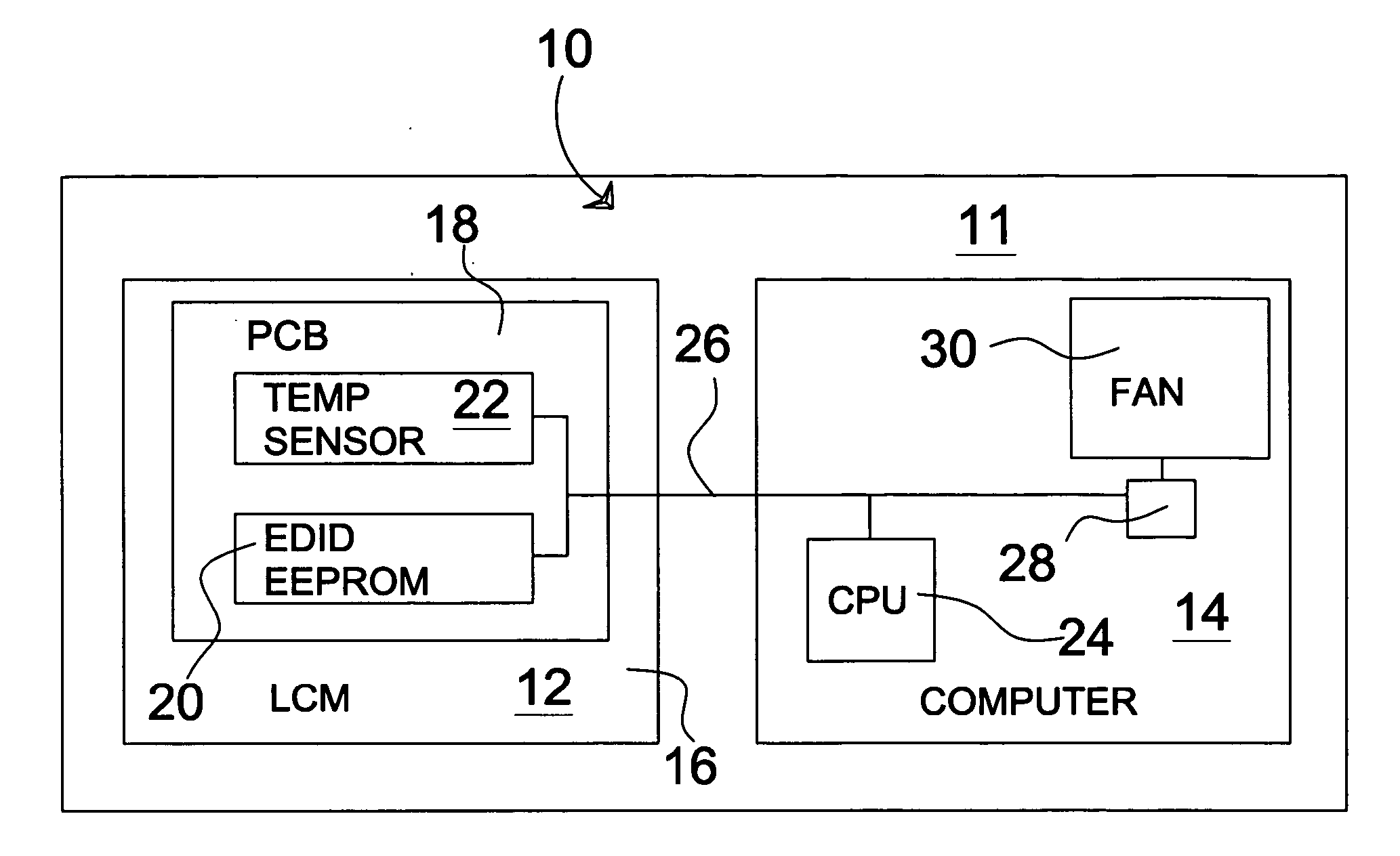
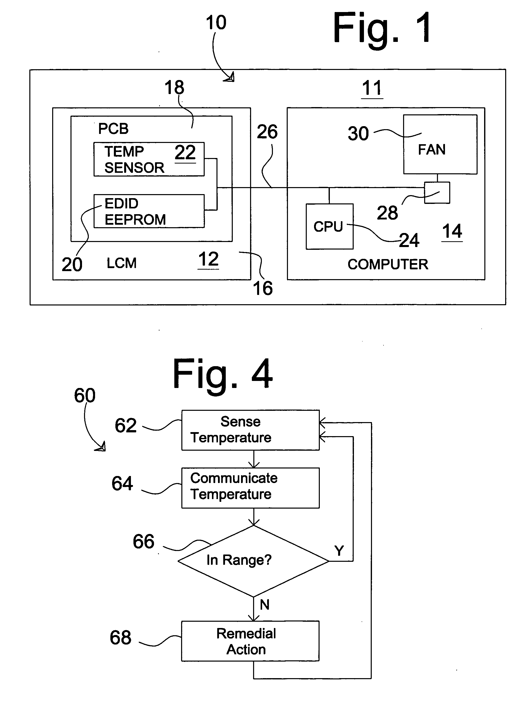
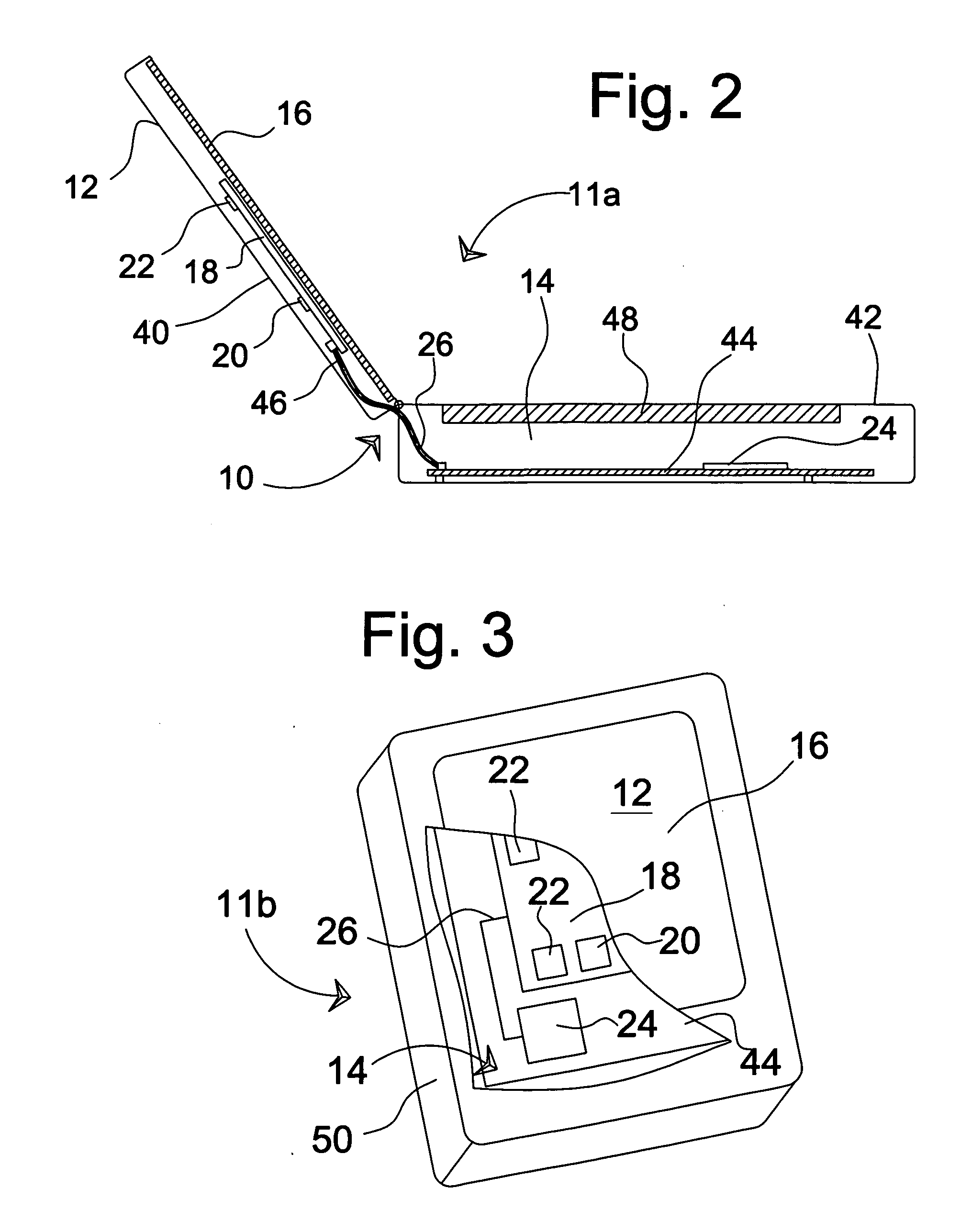
[0023] This invention is described in the following description with reference to the Figures, in which like numbers represent the same or similar elements. While this invention is described in terms of modes for achieving this invention's objectives, it will be appreciated by those skilled in the art that variations may be accomplished in view of these teachings without deviating from the spirit or scope of the present invention. The embodiments and variations of the invention described herein, and / or shown in the drawings, are presented by way of example only and are not limiting as to the scope of the invention. Unless otherwise specifically stated, individual aspects and components of the invention may be omitted or modified, or may have substituted therefore known equivalents, or as yet unknown substitutes such as may be developed in the future or such as may be found to be acceptable substitutes in the future. The invention may also be modified for a variety of applications wh...


PUM


Abstract

A temperature sensing apparatus (10) and associated method (60) wherein a temperature sensor (22) or a plurality of temperature sensors (22) is placed in or in near proximity to a liquid crystal display module (12) of a computer system (11, 11a, 11b). The temperature sensor(s) (22) are placed on, or in near proximity to the liquid crystal display module (12) at positions determined according to the requirements of a particular application. Temperature of the liquid crystal display module (12) is communicated digitally to an associated computer (14) by, for example, a bus such as an inter-integrated circuit interface bus (26). When the temperature exceeds a predetermined limit, remedial action, such as increasing fan speed, reducing speed and or power consumption of other components, or the like, is taken to reduce the temperature.

Description

BACKGROUND OF THE INVENTION [0001] 1. Field of the Invention [0002] The present invention relates generally to the field of personal computers and component parts thereof, and more particularly to an apparatus and method for monitoring and controlling the temperature of monitor devices, particularly liquid crystal display modules (“LCMs”) used in conjunction with certain personal computers. The predominant current usage of the inventive temperature sensing apparatus and method is in preventing problems related with overheating in portable computers, particularly but not exclusively in tablet type computer devices, wherein heat is a particular problem because certain heat producing components may be directly behind the LCM. [0003] 2. Description of the Background Art [0004] Thermal management in computer systems, especially in laptops, is a very challenging issue. Many components, primarily the Central Processing Unit (“CPU”), the Graphics Processing Unit (“GPU”), the hard drive, the...

Claims


Application Information

Patent Timeline
Patent Type & Authority Applications(United States)
IPC IPC(8): G09G5/00
CPCG06F1/206Y02B60/1275G09G2320/041G09G3/3611G09G2360/10Y02D10/00
Inventor XU, GANGLEIBA, AARON M.ZHONG, JOHN Z.
Owner APPLE INC
Why Eureka
Try Eureka