
Air shutter and installation method thereof

a technology of air curtains and air vents, which is applied in the field of air curtains, can solve the problems of large air stream size, difficult formation of air curtains, and weak effect of preventing the intrusion of outside warm air in the upper region of the entrance, and achieves the effects of low cost, easy maintenance, and high efficiency

Inactive Publication Date: 2006-09-07
MAYEKAWA MFG CO LTD
View PDF4 Cites 2 Cited by
  • Summary
  • Abstract
  • Description
  • Claims
  • Application Information

AI Technical Summary

Benefits of technology

The system efficiently interrupts air flow across doorways, preventing outside air intrusion and cold air leakage while minimizing condensation and maintaining visibility and operational access.

Problems solved by technology

However, with said apparatus, a problem is involved that the amount of air to form the air streams is larger compared with an air curtain producing apparatus in which an air curtain is formed with the air spouted out from one side of the doorway.
Therefore, there is a problem that air curtain is difficult to be formed in the upper region of the entrance and the effect of preventing the intrusion of outside warm air in the upper region of the entrance is weak.
Therefore, sufficient effect of interception of outside air cannot be achieved.
With the proposal, although an air curtain 62 is produced in front of the space 65b to intersect air flow between the outside and inside of the building, there remains a problem that the intrusion of outside air from the clearance above the top of the space 65b cannot be prevented.
The white smoke induces poor visibility from outside.
There occurs also a problem that ice is formed on the floor and on the doorway-side end faces of the door 60 and 61 where the inside cold air mixes with the air stream which consists of only outside air of higher temperature.
As has been mentioned above, with lateral flow type air curtain producing apparatuses of prior art, there is a problem that outside air intrudes from the clearance formed above the top of the opened space of doorway when doors are opened.
However, the interception effect is decreased near the floor where the velocity of the air stream is lowest, and white smoke is generated due to the condensation of the moisture in the air stream as a result of mixing of it with the cold air leaking out from inside, inducing poor visibility from outside and also ice is formed on the floor.
With the down-flow type air curtain, as the flow angle of air is constant, stable curtain effect is difficult to be obtained, and when the difference in air temperature between the inside and outside of the building, the effect of interception near the bottom part of the air curtain decreases.
Particularly in the bottom region of the air curtain where the air velocity is small, the air curtain tends to be broken.
As the down-flow type air curtain involves problems as mentioned above, it is difficult to sufficiently prevent the cold air from leaking out from inside.
According to the proposal, although it is possible to prevent the occurrence of white smoke due to the condensation of the moisture in outside hot air as occurred with apparatuses of prior art by forming the circulating interception air stream comprising the hot air interception air stream and cold air interception air stream, the problem concerning efficient interception between inside and outside was not solved enough.

Method used


Image

  • Air shutter and installation method thereof
  • Air shutter and installation method thereof
  • Air shutter and installation method thereof

Examples


first embodiment

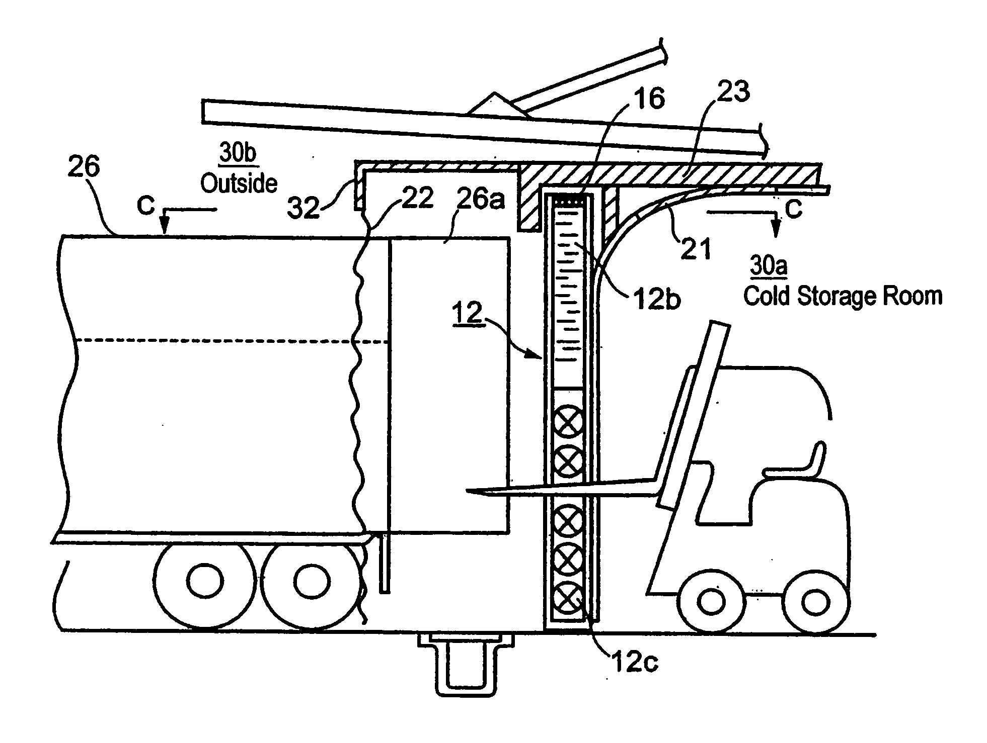
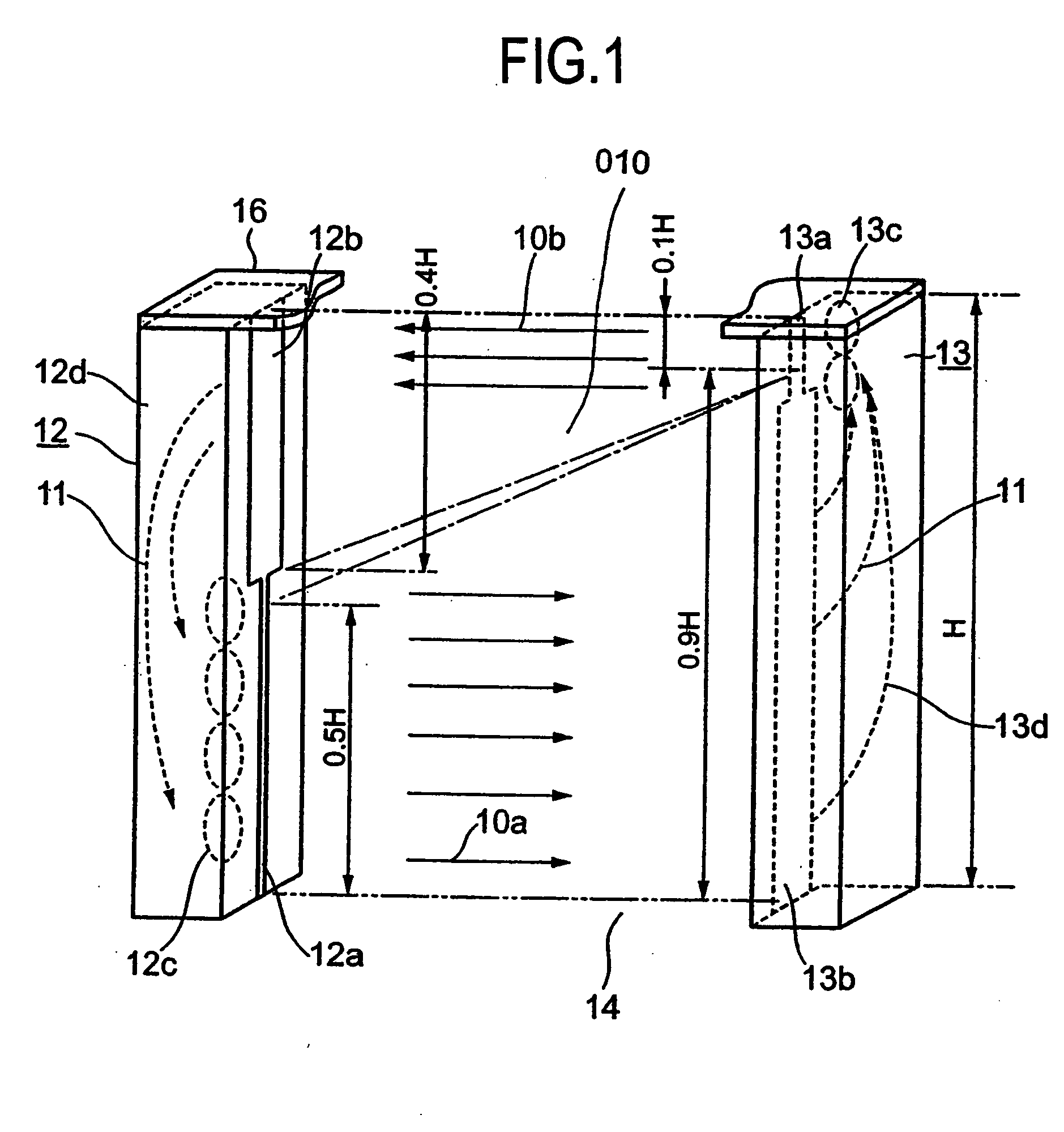
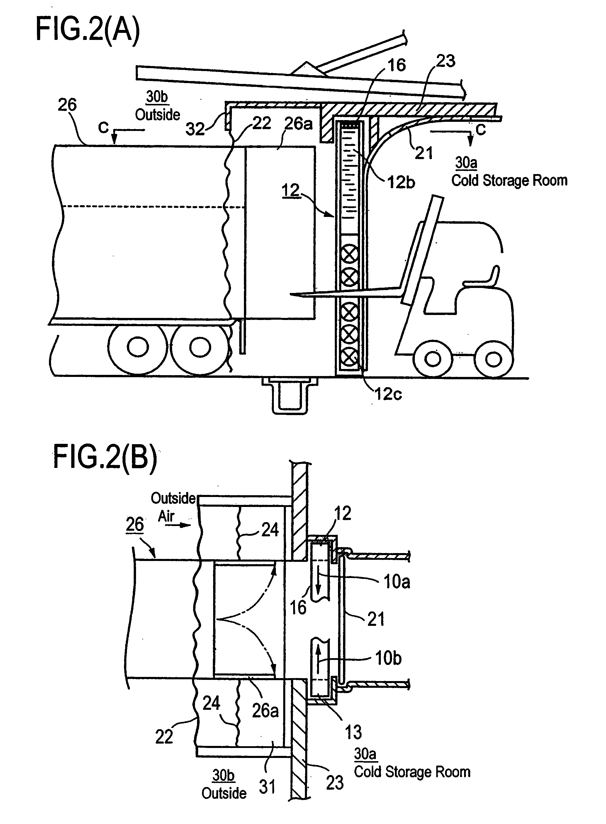
[0072] Referring to FIG. 1, the air shutter according to the present invention is composed of a portal-shaped construction comprising a gatepost 12 for producing a cold air interception air stream, a gatepost 13 for producing a hot air interception air stream, and an upper crossbeam 16 connecting both the gateposts, the portal-shaped construction being installed in front of the doorway of a cold storage. A lower slit nozzle 12a is provided in the lower part of the doorway side face of said gatepost 12, the lower end of the lower slit nozzle 12a reaches the floor 14. Above the lower slit nozzle 12a is provided a suction opening 12b extending upward until it reaches the upper crossbeam 16. Inside the gatepost 12 are provided lower side fans 12c and a suction duct 12d which guides the circulation air 11 sucked from the suction opening 12b to the suction side of said lower side fans 12c.

[0073] On the other hand, an upper slit nozzle 13a is provided in the upper part of the doorway side...

third embodiment

[0097] the fans and slit nozzles of said gatepost 13 side are located in the upper and lower part of the gatepost 13, air is blown by the first fan group 40a located in the upper part toward the suction opening 12b1 of the gatepost 12 opposite to the gatepost 13, at the same time air is blown by the second fan group 40b located in the lower part toward the suction opening 12b2 of the gatepost 12, on the other hand, the suction duct in the gatepost 12 is divided at the intermediate part of the suction duct into the upper and lower suction duct 12d1 and 12d2, the fans and slit nozzles of the gatepost 12 side are located in the upper and lower part of the suction duct 12d1 and 12d2 respectively, air is blown by the third fan group 40c toward the suction opening 13b1 of the gatepost 13 opposite to the gatepost 12, and at the same time air is blown by the fourth fan group 40d toward the suction opening 13b2 of the gatepost 13, so that the fan groups each consisting of a plurality of fan...

fourth embodiment

[0101] In the present invention shown in FIG. 6, a short curtain 46 consisting of a plurality of curtain cloths of different length is hung from an upper crossbeam 16 installed on a gatepost 12 and gatepost 13 for interrupting heat flow between the inside and outside of the opening area 010 in the upper part thereof. The length H1 of the short curtain 46 is about a half the height H of the opening area 010 or shorter in order to form an area 46a below the curtain 46 to allow the easy passing of a cargo vehicle.

[0102] With the fourth embodiment, the effect of interruption of heat flow in the upper part of the opening area 010 can be enhanced by the short curtain 46 in addition to that the difference in temperature between the interception air streams and the cold air inside the storage is decreased by the circulation of the air of the interception air streams.

[0103] Since the short curtain 46 is provided only in the hot air interception zone in the upper part of the opening area 010...


PUM


Abstract

An air shutter of low cost, high efficiency, and easy maintainability is provided, which can interrupt efficiently the flowage of air across a doorway when the door is open based on the consideration of the experimental data of the flowage of air across the opening area of the doorway of a cold storage. The air shutter comprises a gatepost 12 and a gatepost 13 installed at both sides of the opening area of a doorway. The gatepost 12 is provided with a lower slit nozzle 12a, a suction opening 12b, and lower fans 12c and a suction duct 12d inside thereof, on the other hand, the gatepost 13 provided with an upper slit nozzle 13a, a suction opening 13b, and lower fans 13c and a suction duct 13d inside thereof.

Description

CROSS REFERENCE TO RELATED APPLICATIONS [0001] The present application is a division of application Ser. No. 10 / 733,756, filed Dec. 12, 2003, which claims benefit to Japanese priority application no. 2003-149544, filed May 27, 2003, whose disclosure is hereby incorporated by reference in its entirety into the present application.BACKGROUND OF THE INVENTION [0002] 1. Field of the invention [0003] The present invention relates to an air shutter to be installed at the entrance where temperature difference exists between inside and outside thereof for preventing air flow through the entrance, that is, the intrusion of outside air and extrusion of inside cold air. [0004] 2. Description of the Related Art [0005] An air curtain producing apparatus for preventing the intrusion of outside air through the doorway of the thermal insulation door used in a building is disclosed in Japanese Patent No. 37-12183. [0006] Said invention proposes an air curtain producing apparatus composed such that a...

Claims


Application Information

Patent Timeline
Patent Type & Authority Applications(United States)
IPC IPC(8): E06B7/02F24F9/00
CPCF24F2009/007F24F9/00
Inventor OHWADA, SACHIOTSUBATA, KOUICHISAKUMA, SEIICHIAKABOSHI, SHINJIROUYASUTOME, AKIRA
Owner MAYEKAWA MFG CO LTD
Learn More