Cooling fan and image display apparatus

a technology of image display apparatus and cooling fan, which is applied in the direction of liquid fuel engine components, non-positive displacement fluid engines, circumferential flow pumps, etc., can solve the problems of poor efficiency of use as cooling fans, inability to meet the demand for quiet operation, and difficulty in providing sufficient circular area for propeller fans, etc., to achieve effective cooling, avoid stalling, and increase the length of the vanes

Inactive Publication Date: 2006-09-07
SONY CORP
View PDF19 Cites 92 Cited by
  • Summary
  • Abstract
  • Description
  • Claims
  • Application Information

AI Technical Summary

Benefits of technology

[0011] The present invention was conceived in order to solve the problems described above and the present invention aims to provide a cooling fan that does not limit the fan installation conditions, is capable of efficiently cooling a backlight unit of a display panel, and has a quieter operation, and to also provide an image display apparatus equipped with such cooling fan.

Problems solved by technology

However, there are the following problems for a television such as the plasma display panel mentioned above.
Factors such as the apparatus design and installation conditions for the fan make it difficult to provide sufficient circular area for a propeller fan.
In addition, although a reduction in the fan tip speed is desired in order to satisfy demands for extremely quiet operation, a larger circular area becomes necessary to achieve the required air flow, and therefore there arises a problem that the demand for quiet operation cannot be satisfied.
Since such fans generate airflows in all directions of the rotating surfaces, there are the problems of poor efficiency for use as cooling fans and a high noise level.

Method used


Image

  • Cooling fan and image display apparatus
  • Cooling fan and image display apparatus
  • Cooling fan and image display apparatus

Examples


Embodiment Construction

[0043] Hereinafter, preferred embodiments of a cooling fan and an image display apparatus according to the present invention will now be described with reference to the attached drawings.

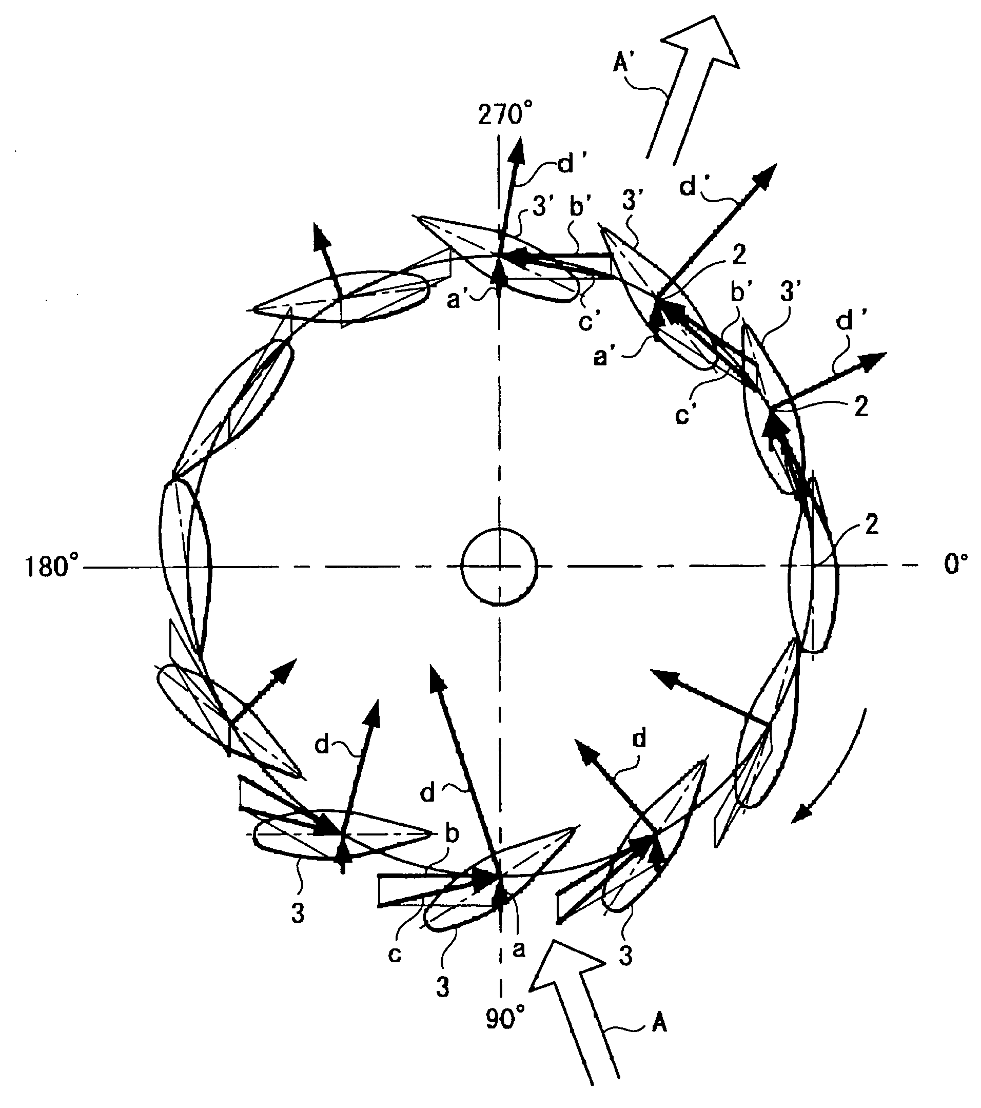
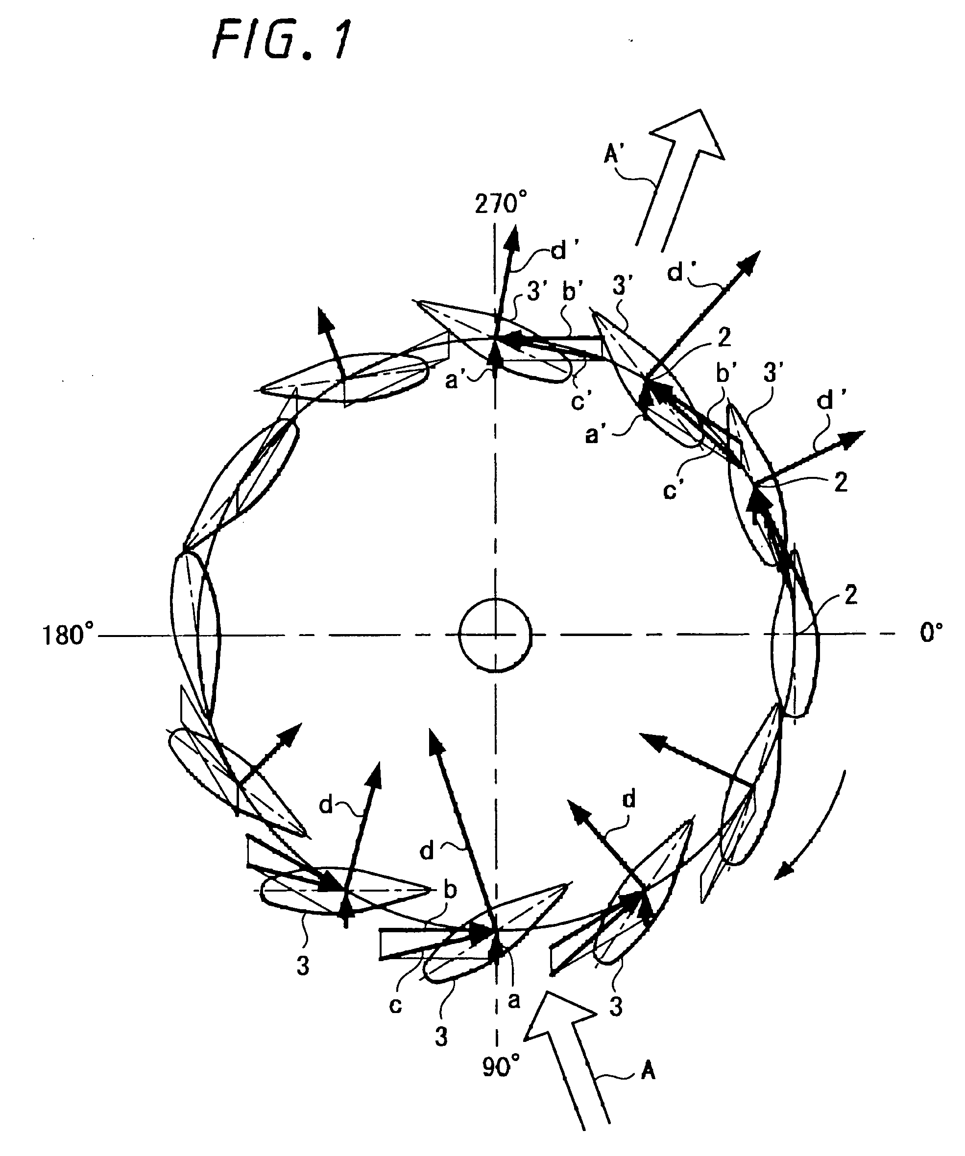
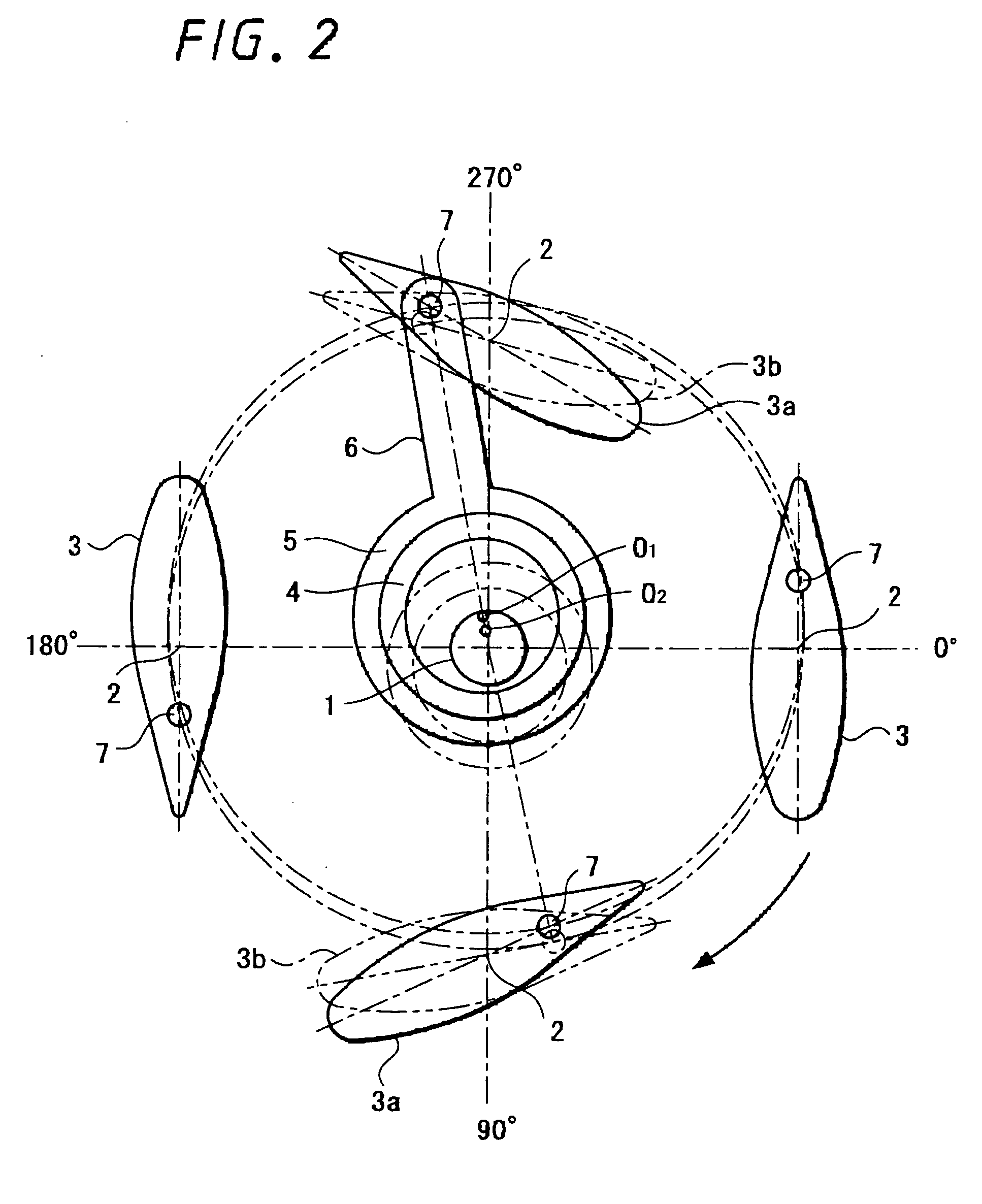
[0044] First, the concept behind the cooling fan will be described with reference to FIG. 1.

[0045] The cooling fan can generate an air flow in one direction perpendicular to a rotational shaft 1, and includes a plurality of parallel revolution shafts 2 that revolve as a single body around the rotational shaft 1. Vanes 3 are rotatably provided on the revolution shafts 2 and by rotationally driving the vanes 3 using the rotational shaft 1 in the clockwise direction shown by the arrow in FIG. 1, lift is generated by the rotated vanes 3 at predetermined revolution angles, thereby producing an airflow in one direction.

[0046] Here, the lift produced by each vane 3 in FIG. 1 is defined by the expression given below.

Lift=Cl·0.5·ρv2   [Expression 1][0047] where, Cl: inclination of vane [0048]ρ: density [...


PUM


Abstract

A cooling fan is provided that does not place limitations on the installation conditions for the fan, is capable of cooling a backlight unit of a display panel with high efficiency, and produces less noise during operation. Also provided is an image display apparatus equipped with the cooling fan. The cooling fan includes a fan rotator composed of a rotational shaft that is rotationally driven by a driving motor and two vanes that have parallel revolution shafts that rotate together with the rotational shaft, are freely rotatable on the shafts, face one another, and revolve around the rotational shafts and a vane angle control unit that implements control so that each vane has a maximum rotation angle when a revolution angle of the vanes is in a vicinity of a first revolution angle and each vane has a rotation angle of 0° when a revolution angle of the vane is in a vicinity of a second revolution angle that is perpendicular to the first revolution angle. By rotating the fan rotator, a wind in a single direction perpendicular to the rotational shaft is generated to cool a back light unit of a flat panel display, for example.

Description

CROSS REFERENCES TO RELATED APPLICATIONS [0001] The present invention contains subject matter related to Japanese Patent Application JP 2004-344756 filed in the Japanese Patent Office on Nov. 29, 2004, the entire contents of which being incorporated herein by reference. BACKGROUND OF THE INVENTION [0002] 1. Field of the Invention [0003] The present invention relates to a cooling fan that can be favorably used in a flat panel display apparatus such as a thin-screen television and to an image display apparatus. In more detail, the present invention relates to a cooling fan for cooling a backlight unit that is a high-temperature region in a flat panel display apparatus, the cooling fan being especially capable of uniformly cooling the backlight unit of a large flat panel display apparatus with high efficiency and operating more quietly than conventional fans. [0004] 2. Description of the Related Art [0005] Fans are conventionally used in a flat panel display apparatus such as a thin-sc...

Claims


Application Information

Patent Timeline
Patent Type & Authority Applications(United States)
IPC IPC(8): F24F7/00
CPCF04D17/04F04D29/30F24F7/007H04N5/66
Inventor KIMURA, AKIRA
Owner SONY CORP
Why Eureka
Try Eureka