

Method and device for steering vehicle having no contact with track
- Summary
- Abstract
- Description
- Claims
- Application Information
AI Technical Summary
Benefits of technology
Problems solved by technology
Method used
Image

Examples
first embodiment
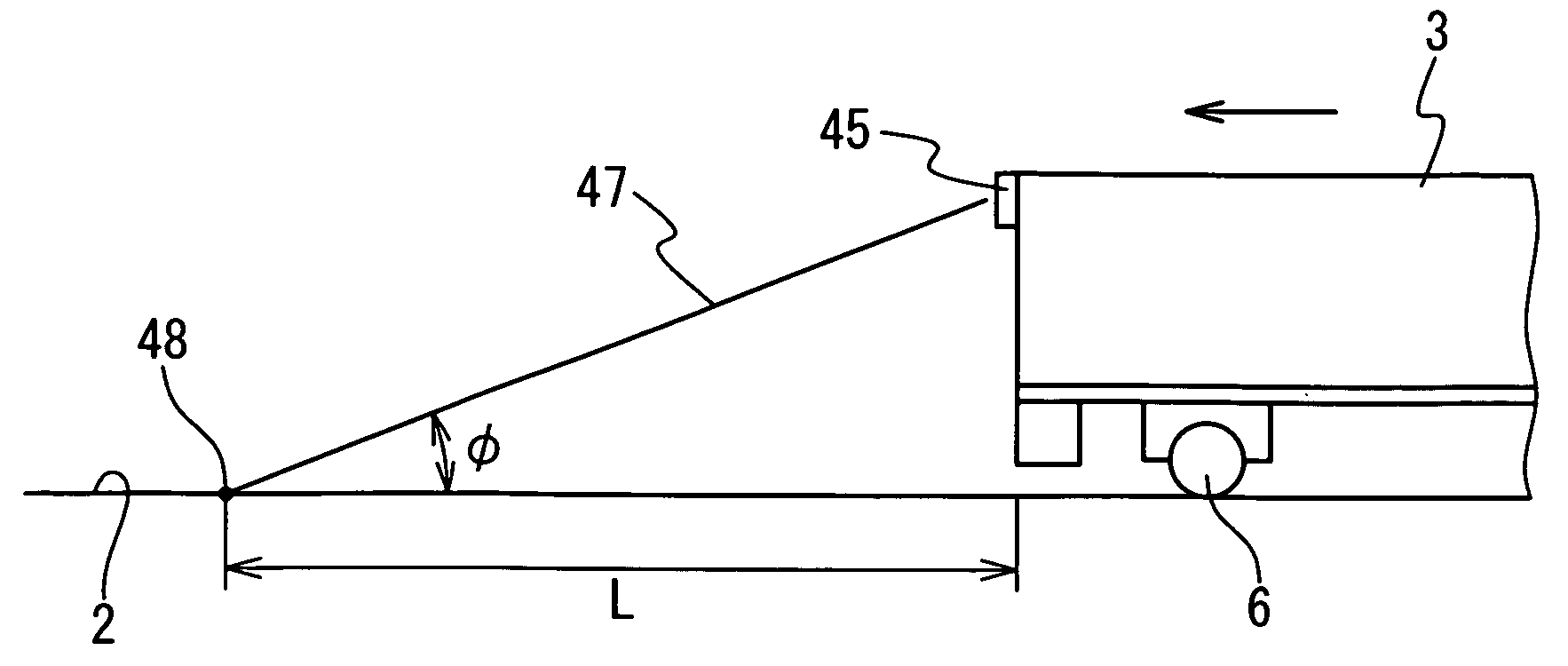
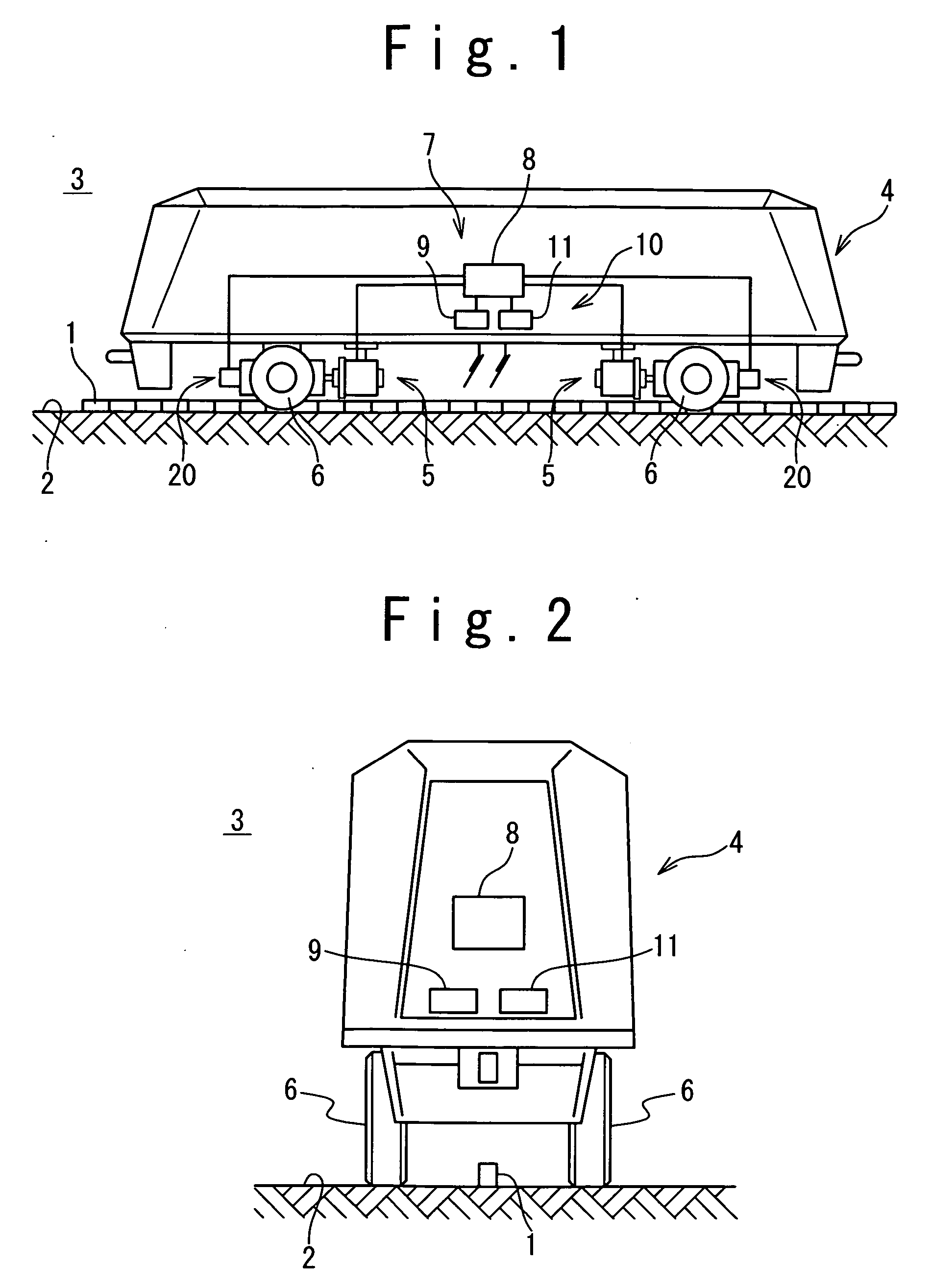
[0054]FIG. 1 is a diagram showing the steering apparatus of the rail non-contact vehicle according to the present invention. Referring to FIG. 1, a guide line 1 is provided on a dedicated rail plane 2 to define a rail reference. The dedicated rail plane 2 is formed linearly or curvedly. The guide line 1 is shown in FIG. 1 such that it projects from the rail plane 2. However, the guide line 1 may be formed to be embedded in the rail plane 2. The vehicle 3 is provided with a vehicle main body 4 and a cart 5. The cart 5 is supported by the dedicated rail plane 2. The vehicle main body 4 is supported on the rail plane 2 by the cart 5 in such a manner that the vehicle main body 4 can turn freely around a perpendicular axis or an axis normal to the rail plane. The cart 5 is provided with wheels 6.
[0055] The steering system is provided with a control section 10 as a non-mechanical steering system section, and a drive section 20 as a mechanical steering system section. The steering system i...
second embodiment
The deviation ΔW is processed similarly to the position deviation ΔD shown in the second embodiment, such that the absolute value of deviation ΔW (=W2−W1) becomes small.
[0094] Referring to FIG. 16, the deviation detection method according to the fifth embodiment of the present invention will be described. Referring to FIG. 16, safe guide rings 53 are added to the vehicle 3 of the FIG. 12 in the fifth embodiment of the present invention. The safe guide ring 53 is provided on either side of the main body of the vehicle 3 or the cart 5. A rotation shaft 54 of the safe guide ring 53 is parallel to the opposing surface of the curbstone 43 on either side. The safe guide ring 53 does not contact the curbstone 43. In this case, the construction cost of the safe guide ring 53 which does not contact the curbstone 43 is significantly lower compared with the construction cost of the well-known guide rail for guide rails. There is no noise generated between the curbstone 43 and the safe guide ri...
seventh embodiment
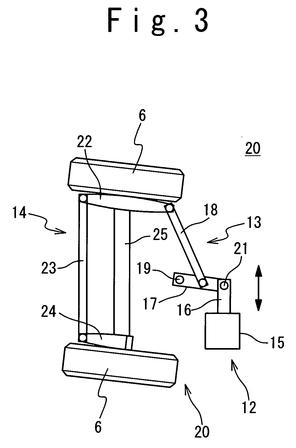
[0097] Referring to FIG. 18, the drive section 20 of the steering system used in the steering apparatus of the rail non-contact vehicle according to the present invention will be described. Referring to FIG. 18, the present embodiment realizes the above-mentioned real time high precision route control and the safety associated with the control. The feature is achieved by using a ball screw and a safety bar, and adding a safe clutch.
[0098] The drive section 20 is provided with the actuator 12, the first link mechanism 13, and the second link mechanism 14. An actuator fixed section 55 fixedly supported by the cart 5 is equivalent to the above-mentioned actuator main body 15. An actuator movable section 56 which moves forward and backward to the actuator fixed section 55 is equivalent to the above-mentioned piston rod 16. A nut 57 is fixed to the actuator fixed section 55. A ball screw 58 screwed in the nut 57 is rotatably supported by bearings 60 and 61 which are fixed to the actuator...
PUM
 Abstract
Description
Claims
Application Information